Do you have a question about the Trane Oxbox J4AH4P24B1A00AA and is the answer not in the manual?
Multiple warnings highlight electrical hazards, proper servicing, and installation procedures to prevent injury or death.
Information regarding California Proposition 65 chemical warnings for products, including fiberglass insulation and formaldehyde.
Proper leveling, drainage slope, and required clearances for installation and maintenance are detailed.
Flexibility in positioning for upflow, downflow, and horizontal applications with direct drive motors is explained.
Default factory configuration for vertical upflow, with instructions for ducted return air.
Procedure for converting to vertical downflow, including breaker orientation and coil repositioning.
Default horizontal right configuration and conversion to horizontal left with coil repositioning.
Guidance for installing in unconditioned spaces, including coil rail removal to minimize sweating.
Details on power supply wiring, branch circuit disconnects, conductor types, and wire size requirements.
Guidelines for low voltage control wiring, separation from power wiring, and recommended wire gauge.
Critical information on permanent unit grounding requirements, methods, and compliance with codes.
Tables showing CFM, Watts, and Current for various motor speeds and static pressures.
Important notes regarding airflow, duct design, diffusers, balancing for optimal system performance and noise.
Compliance with NFPA, duct material, insulation, and design standards like ACCA Manual D.
Warning against connecting return ductwork to other heat-producing devices to prevent fire or explosion.
Instructions to keep coil sealed, use nitrogen flow, and protect components during brazing.
Install tubing to allow access, seal gaps, and insulate connections to prevent vapor leaks.
External filter is required; placement affects system performance, component life, and efficiency.
Avoid double filtering or filtering supply air; consult professionals for high-efficiency filters.
Details on filter rail placement, filter cover, and manual bolt for external filter installation.
Steps for removing, cleaning, and reinstalling the air filter, including cleaning methods and direction.
Wiring diagram illustrating thermostat connections for AC systems, showing terminals and unit connections.
Wiring diagram illustrating thermostat connections for HP systems, showing terminals and unit connections.
Diagrams for indoor unit wiring for PSC motor AC/HP systems and single auxiliary heat mode.
Wiring diagrams for indoor units with various electric heat kits, including circuit breakers and fuses.
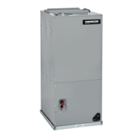
This document provides installation, adjustment, and operation instructions for the Oxbox J4AH4P Series High-Efficiency Air Handlers, designed for 1.5-5 ton systems using R410A or R22 refrigerant. It is intended for qualified, licensed service personnel to ensure proper and safe installation and maintenance.
The Oxbox J4AH4P Series Air Handlers are designed to provide conditioned air as part of a heating and air-conditioning system. These units are versatile, supporting multi-position installation, including upflow, downflow, horizontal right, or horizontal left configurations. They are equipped with multi-speed blower motors, allowing for a selection of air volumes to match various applications and desired airflow requirements. The units are compatible with field-installed electric heater kits, available in 5, 7.5, 10, 15, and 20 kW options, which can be added as accessories to provide supplemental heating. The air handlers are designed to work with both AC and heat pump systems, with specific control wiring diagrams provided for each. They feature factory-sealed cabinets, certified to achieve a 2% or less air leakage rate at 1.0 inch water column, contributing to energy efficiency.
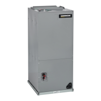
The air handlers offer flexible installation options to accommodate different spatial requirements. The default factory configuration is vertical upflow or horizontal right, but units can be field-converted to horizontal left or downflow. For vertical downflow conversion, the indoor coil assembly is removed and reinstalled 180 degrees from its original position. Similarly, for horizontal left conversion, the indoor coil assembly is rotated 180 degrees. Multiple electrical entry locations are provided for convenience during wiring. The units include an integrated filter rack with tool-less door access, simplifying filter maintenance. Condensate drainage is managed by primary and secondary condensate drain fittings, with the drain pan made of polymer with a UVC inhibitor. Horizontal and vertical condensate drain pans are standard, and secondary drain pan kits are recommended for horizontal installations over finished ceilings or living spaces to prevent potential water damage. The unit must be installed in a level position to ensure proper condensation drainage, though a slight rise (up to 1/4 inch) towards the drain is permissible. Proper grounding is essential for safety, and connections for control wiring are made via low voltage pigtails extending from the top of the air handler in an upflow position, or through knockouts on the sides.
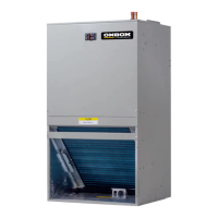
Ease of maintenance is a key design aspect of the J4AH4P Series Air Handlers. The units feature a dual front panel design, which allows for convenient access to internal components. Both the blower and coil assemblies are designed to easily slide out, facilitating inspection, cleaning, or replacement. The fully-insulated cabinet design helps maintain thermal performance and reduces condensation on the exterior, especially in hot and humid environments. The integrated filter rack with tool-less door access makes filter removal and cleaning straightforward. Filters are not factory-installed and must be added during installation. Regular filter cleaning or replacement is crucial for maintaining optimal airflow and system performance, as reduced airflow can shorten the lifespan of major components. The manual provides instructions for removing and cleaning the air filter, recommending vacuuming or using pure water with a soft brush and mild detergent for heavy dust accumulation. Provisions for disconnecting and cleaning the primary drain line are included, with a recommended 3-inch trap installed as close to the unit as possible to ensure complete drainage and prevent blockages. The design also allows for easy replacement of the piston to a TXV (Thermostatic Expansion Valve), if required for specific system combinations or efficiency ratings. Before any servicing or installation, it is critical to disconnect all power to the unit to prevent electrical shock. The manual emphasizes that maintenance should be performed by trained, qualified service personnel, with consumer service limited to filter cleaning/replacement.
| Model | J4AH4P24B1A00AA |
|---|---|
| Product Category | Air Handlers |
| Brand | Trane |
| Voltage | 208/230V |
| Phase | 1 |
| Refrigerant | R-410A |
| Motor Type | ECM |
| Nominal Cooling Capacity | 2 Tons |
| Nominal Heating Capacity | 24, 000 BTU/h |
| Cabinet Type | Metal |