PKGP-SVX010B-EN
27
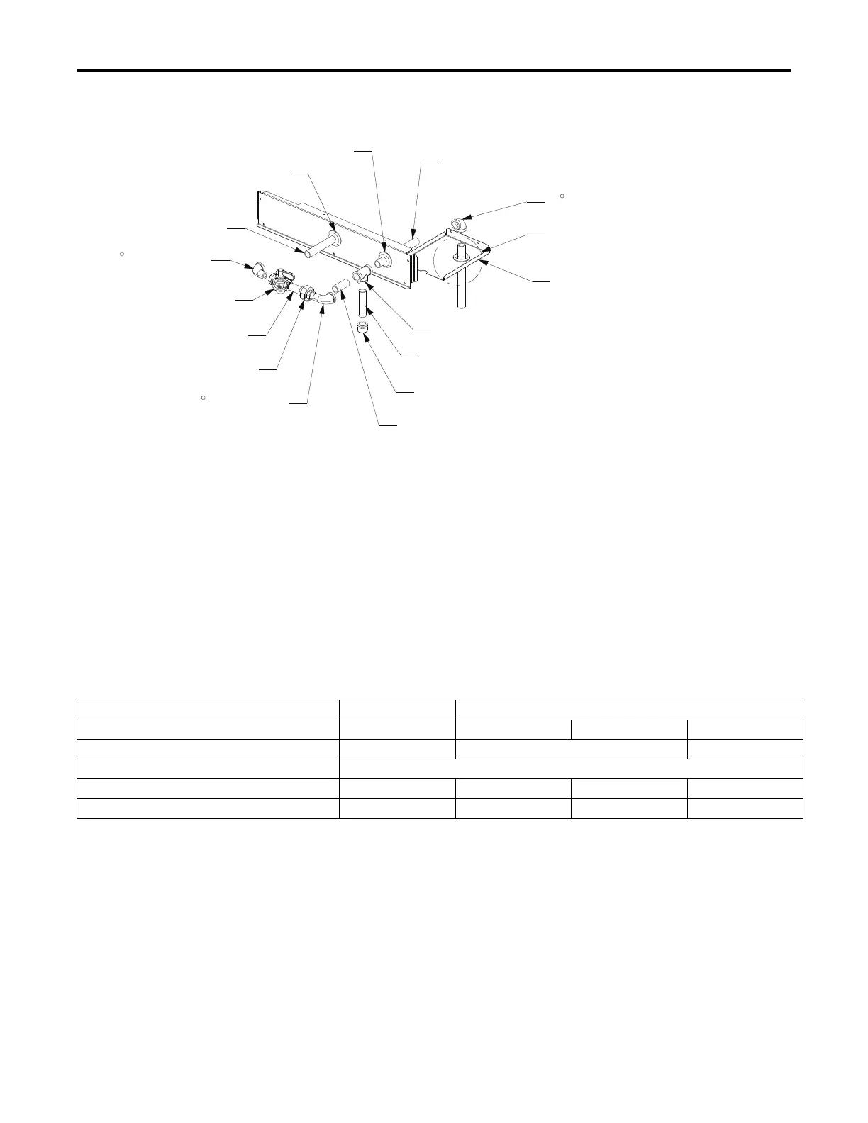
Figure 27. Through-the-base gas pipe assembly for DSJ(150-300)A
Support Plate
90 Elbow
3/4" x 8 1/2" Pipe Nipple
Tee
3/4" x 4" Pipe Nipple
3/4" x 2 1/2" Pipe Nipple
Cap
90 StreetElbow
90 Street Elbow
3/4" x 6 1/2" Pipe Nipple
3/4" x 2 1/2" Pipe Nipple
Gas Shut-off Valve
Pipe Union
SEE DETAIL A
Grommet
Grommet
For detailed Through-the-Base Gas Installation
instructions, refer to the Through-the-Base Gas Piping 3 to
25 Tons Gas/Electric Packaged Units Installation
Instructions (ACC-SVN17*-EN) provided with Through-the-
Base Gas Installation kit.
Requirements of Gas Heat
The unit gas train and optional through-the-base gas shut-
off valve are rated at 0.50 PSIG maximum. A pressure
reducing regulator is recommended to prevent this
maximum from being exceeded. These components must
be isolated during field gas piping test that exceed 0.50
PSIG. It is recommended that the field piping be capped
prior to the unit gas train or optional through-the-base gas
shut-off valve if present.
• Gas supply line properly sized and connected to the
unit gas train.
• All gas piping joints properly sealed.
• Gas piping leak checked with a soap solution. If piping
connections to the unit are complete, do not pressurize
piping in excess of 0.50 PSIG or 14-inch W.C. to
prevent component failure.
• Drip leg installed in the gas piping near the unit.
• Flue Exhaust clear of any obstruction.
Table 6. Gas heat data - standard efficiency
DSJ150A
DSJ(180-300)A
Heating Input Rate — Btu/h
150,000-250,000 250,000 320,000 400,000
Minimum Supply Gas Pressure NG/LP (in. w.c.)
4.5/11.5 4.5/11.5 6/11.5
Maximum Supply Gas Pressure (in. w.c.)
14
Manifold Gas Pressure – 1st Stage -NG (in. w.c.)
1.8 1.7 1.8 1.7
Manifold Gas Pressure – 2nd Stage -NG (in. w.c.)
3.5 3.3 3.5 3.3
Condensate Drain Configuration
An evaporator condensate drain connection is provided on
each unit. Refer to the ductwork section in the Installation
chapter for the appropriate drain location.
A condensate trap must be installed at the unit due to the
drain connection being on the “negative pressure” side of
the fan. Install the P-Trap using the guidelines in Figure
28, p. 28.
A condensate drain line must be connected to the P-Trap.
Pitch the drain lines at least 1/2 inch for every 10 feet of
horizontal run to assure proper condensate flow. Do not
allow the horizontal run to sag causing a possible double
trap condition which could result in condensate backup due
to “air lock”.
Installation