46
RT-SVX075C-EN
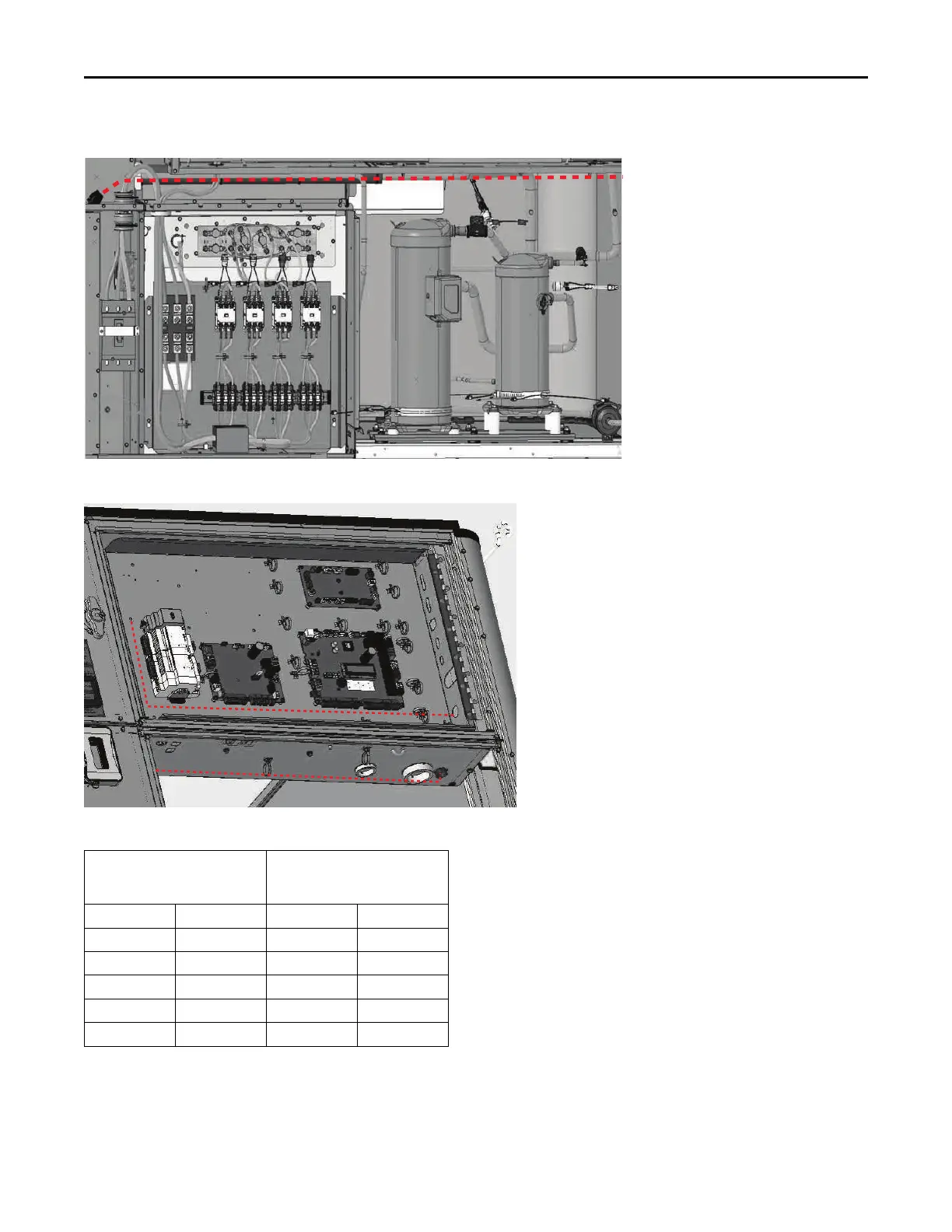
Figure 68. Low voltage wiring — D cabinet
Figure 69. Main control panel low voltage wiring
Table 9. Recommended wire lengths
Wire Size
Maximum recommended wire
length from unit controller to
sensor
AWG mm
2
Meters Feet
22 0.33 0–46 0–150
20 0.50 47–73 151–240
18 0.75 74–117 241–385
16 1.30 118–185 386–610
14 2.00 186–296 611–970
Note: The total resistance of these low voltage wires must not exceed 2.5
Ω/conductor. Any resistance greater than 2.5 Ω may cause the
control to malfunction due to an excessive voltage drop.
Controls using DC Analog Input/Outputs
(Standard Low Voltage Multi conductor
Wire)
Before installing any connecting wiring between the unit
and components utilizing a DC analog input\output signal,
refer to the Dimensions and Weights chapter for the
electrical access locations provided on the unit.
• Table 10, p. 47 lists the conductor sizing guidelines that
must be followed when interconnecting the DC binary
output devices and the system components utilizing a
DC analog input/output signal to the unit.
Installation