Do you have a question about the Trane Precedent YZC036E and is the answer not in the manual?
Defines the three types of advisories: WARNING, CAUTION, NOTICE.
Covers critical safety warnings for wiring, grounding, and PPE requirements.
Discusses environmental concerns and responsible refrigerant handling.
Adherence to EHS policies, copyright, trademarks, and revision history.
Provides important notes and clarifications regarding model number configurations.
Procedures for inspecting the unit upon arrival and proper storage guidelines.
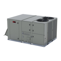
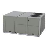
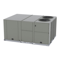
Description of unit features, nameplates, and optional components like Clogged Filter Switch.
Details on Compressor Disable, Protection, Drain Pan Switch, DLTS, Humidity, Economizer, Frost Control, High Pressure Control, High Temp Sensor.
Covers Human Interface, Low Pressure Control, VAV, Phase Monitor, Power Exhaust, Zone Sensors, and Communication Interfaces.
Details Remote Zone Sensors, Communication Interfaces, RTOM, and Variable Air Volume control.
Explains Smoke Detector functionality and Supply Fan Failure Input.
Groups various zone sensors and input devices for system control.
Warns about fiberglass hazards and required PPE and first aid.
Illustrates clearances, weights, and center of gravity for unit installation.
Warns about hazards of lifting heavy components and proper lifting procedures.
Presents weights and center of gravity dimensions for gas/electric models.
Lists net weights for various factory-installed options and accessories.
Provides dimensional views for 3-ton ultra high efficiency units.
Illustrates downflow utilities for 3-ton units with through-the-base connections.
Shows dimensions for 3-ton horizontal airflow supply and return.
Shows clearance requirements and roof opening sizes for 3-ton units.
Shows roof curb dimensions for 3-ton units.
Illustrates downflow duct connections for field fabrication on 3-ton units.
Shows dimensions related to economizer and fresh air damper options on 3-ton units.
Illustrates dimensions for economizer and barometric relief damper hood on 3-ton units.
Shows swing diameter for hinged doors on 3-ton units.
Presents general dimensions for 4 to 5 ton ultra high efficiency units.
Illustrates downflow utilities for 4-5 ton units with through-the-base connections.
Shows required gas pipe height for 3-ton Y_C models.
Illustrates unit clearance and roof opening for 4-5 ton units.
Shows roof curb dimensions for 4-5 ton units.
Illustrates downflow duct connections for field fabrication on 4-5 ton units.
Shows dimensions for economizer/fresh air damper on 4-5 ton units.
Shows swing diameter for hinged doors on 4-5 ton units.
Presents general dimensions for 6 to 8.5 ton ultra high efficiency units.
Illustrates unit clearance and roof opening for 6-8.5 ton units.
Shows roof curb dimensions for 6-8.5 ton units.
Illustrates downflow utilities for 6-8.5 ton units with through-the-base connections.
Illustrates duct connections for field fabrication on 6-10 ton units.
Shows dimensions related to the power exhaust feature on 6-8.5 ton units.
Shows swing diameter for hinged doors on 6-8.5 ton units.
Shows dimensions for economizer/fresh air damper on 6-10 ton units.
Shows required gas pipe height for 6-10 ton YZC models.
Illustrates unit clearance and roof opening for 10 ton units.
Shows roof curb dimensions for 10 ton units.
Shows dimensions related to the power exhaust feature on 10 ton units.
Shows swing diameter for hinged doors on 10 ton units.
Guidelines for foundation installation and ductwork connections.
Instructions for roof curb installation and warnings about combustible materials.
Covers safe rigging procedures and installation checklists.
Details TCO1 tripping values and horizontal discharge conversion steps.
Instructions for installing smoke detectors and wireless communication interfaces.
Covers main electrical power, wiring, grounding, and through-the-base gas installation.
Details gas heat requirements and condensate drain configuration.
Identifies components of the Ultra Low NOx Gas Furnace option.
Procedures for drain pan removal and filter installation.
Guidelines for field-installed power and control wiring, including safety.
Covers electrical power connection requirements.
Guides on wiring DC analog inputs/outputs and conductor sizing.
Procedures for checking voltage imbalance and electrical phasing for motors.
Information on crankcase heaters and ReliaTel™ control initialization.
Outlines different test modes for component operation verification.
Explains different test modes for component operation.
Explains ReliaTel™ control initialization and self-diagnostics.
Steps for verifying airflow and understanding the unit's sequence of operation.
Explains operation modes including cooling, heating, and enhanced dehumidification.
Details economizer operation and warm-up controls like MWU and DWU.
Explains how the return air smoke detector functions.
Covers economizer startup and setting the minimum damper position.
Procedures for starting and checking compressors, including scroll compressor operation.
Steps for starting gas heat units and resetting the RTRM.
Details how to verify dip switch settings for unit models.
Final checks after pre-start and startup procedures.
Steps for programming panels and final unit inspections before operation.
General safety precautions for maintenance tasks involving hazards.
Lists tasks for monthly maintenance, including filters and coil checks.
Provides instructions for cleaning microchannel and round tube coils.
Covers coil damage warnings and cleaning procedures for MCHE coils.
Details cleaning procedures for RTPF coils, including chemical use warnings.
Outlines annual maintenance tasks and recording operational data.
Steps for checking ReliaTel™ module diagnostics and system status.
Methods for checking system status using LED indicators or voltage readings.
Lists failure causes and procedures for resetting cooling/ignition lockouts.
Checks voltage between terminals for system failure indication.
Verifies heat failure using the Ignition Module (IGN) LED indicator.
Identifies causes for cooling failure and related component checks.
Checks for supply fan proving switch, clogged filter, and condensate overflow switch issues.
Procedures for testing zone temperature sensors and setpoints.
Explains the function of the SERVICE LED for clogged filters.
Procedure for temporary unit operation without a zone sensor.
Explains RTRM default mode operation when building management input is lost.
Explains fault codes and troubleshooting for economizer control.
Lists drawing numbers for various control, power, and connection wiring diagrams.
Details the warranty terms for the Combination Gas Electric Air Conditioner.
| Model | YZC036E |
|---|---|
| Category | Air Conditioner |
| Energy Efficiency Ratio (EER) | 11.5 |
| Heating Seasonal Performance Factor (HSPF) | Not Applicable |
| Refrigerant | R-410A |
| Compressor Type | Scroll |
| Voltage | 208/230 V |
| Frequency | 60 Hz |
| Sound Level (Outdoor Unit) | 74 dB |
| Cooling Capacity | 36, 000 BTU/h |