RT-SVX071D-EN
41
Requirements of Gas Heat
The unit gas train and optional through-the-base gas shut-
off valve are rated at 0.50 PSIG maximum. A pressure
reducing regulator is recommended to prevent this
maximum from being exceeded. These components must
be isolated during field gas piping test that exceed 0.50
PSIG.
Important: It is recommended that the field piping be
capped prior to the unit gas train or optional
through-the-base gas shut-off valve if present.
☐ Gas supply line properly sized and connected to the
unit gas train.
☐ All gas piping joints properly sealed.
☐ Gas piping leak checked with a soap solution. If piping
connections to the unit are complete, do not pressurize
piping in excess of 0.50 PSIG or 14-inch w.c. to prevent
component failure.
☐ Drip leg installed in the gas piping near the unit.
☐ Flue exhaust clear of any obstruction.
☐ Supply and manifold pressures should be checked
during unit commissioning (see Table 7, p. 41 and
Table 8, p. 41).
Table 7. Gas heat data - supply and manifold
pressure requirements – two-stage gas
YSJ(072-150)* YSJ(180-300)*
Heating Input Rate –
Btu/h
80,000 – 250,000 250,000 320,000 400,000
Minimum Supply Gas
Pressure NG/LP (in. w.c.)
4.5/11.5 4.5/11.5 6/11.5
Maximum Supply Gas
Pressure (in. w.c.)
14
Manifold Gas Pressure –
1st Stage - NG (in. w.c.)
1.8 1.7 1.8 1.7
Manifold Gas Pressure –
2nd Stage - NG (in. w.c.)
3.5 3.3 3.5 3.3
Table 8. Gas heat data - supply and manifold
pressure requirements - modulating gas
Digit 10 = B models
Heating Input Rate – Btu/h
80,000 – 400,000
Minimum Supply Gas Pressure NG/LP (in. w.c.)
5/11.5
Maximum Supply Gas Pressure (in. w.c.)
14
Manifold Gas Pressure – Full Gas Input Rate - NG/
LP (in. w.c.)
3.5/10
Modulating Gas Heat
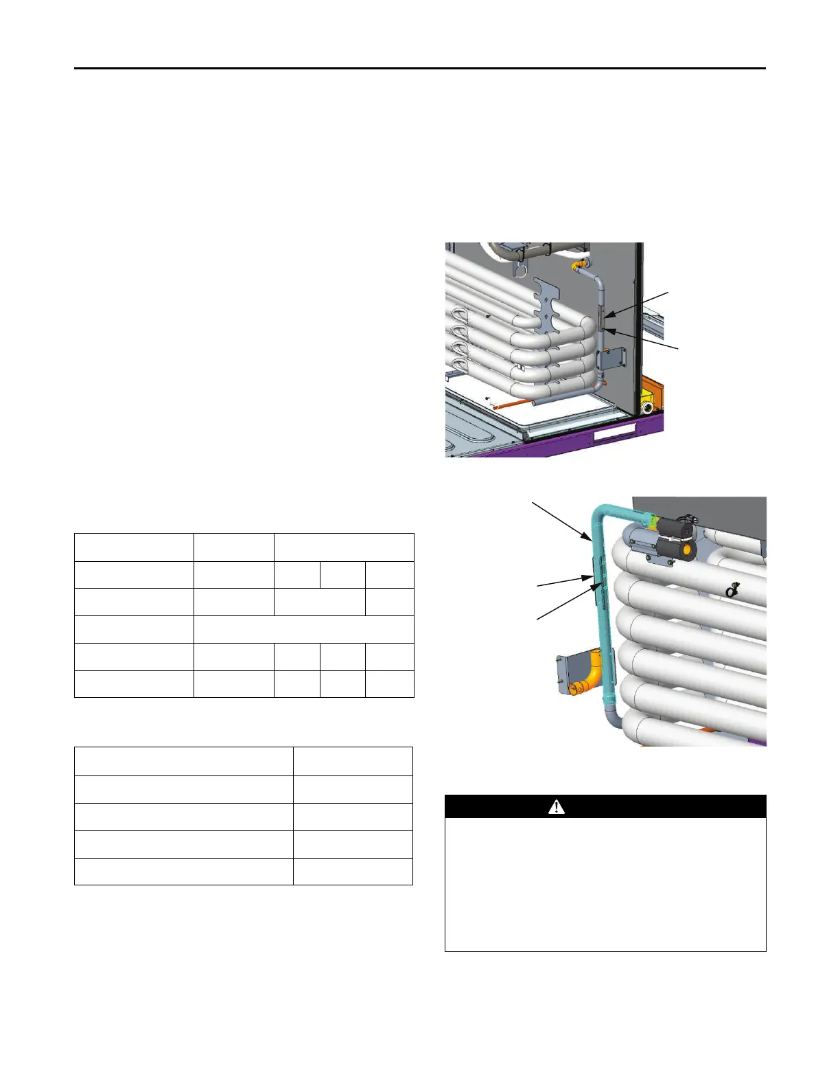
For models YSJ(072,090,102,120,150)***B(H,L):
1. Confirm the vertical slide bracket on the DAS vertical
tube is positioned to block all the hole(s) for downflow
configuration.
Note: Number of holes will vary. Verify bracket is
covering all holes in the vertical tube, regardless
of quantity.
2. Removal of horizontal duct supply cover is required to
view DAS tubing located behind the heat exchanger
tubes.
Figure 63. Downflow position shown
Bracket adjustment
screw
Vertical slide bracket
downflow position
Figure 64. Vertical tube hole(s) location
Hole or holes
located here
Vertical slide bracket
positioned to block
hole(s)
Vertical DAS tube
Condensate Drain Configuration
WARNING
Hazardous Voltage!
Failure to disconnect power before servicing could
result in death or serious injury.
Disconnect all electric power, including remote
disconnects before servicing. Follow proper lockout/
tagout procedures to ensure the power can not be
inadvertently energized. Verify that no power is
present with a voltmeter.
An evaporator condensate drain connection is provided on
each unit. Refer to the ductwork section in the Installation
chapter for the appropriate drain location.
Installation