CAUTION!
(1) The high-voltage and low-voltage lines should pass through the rubber rings at different
electric box covers.
(2) The high-voltage and low-voltage lines should be fixed separately and securely, with internal
big clamps for the former and small clamps for the latter.
(3) Tighten the indoor/outdoor connection cord and power cord respectively on the terminal
boards with screws. Faulty connection may cause a fire.
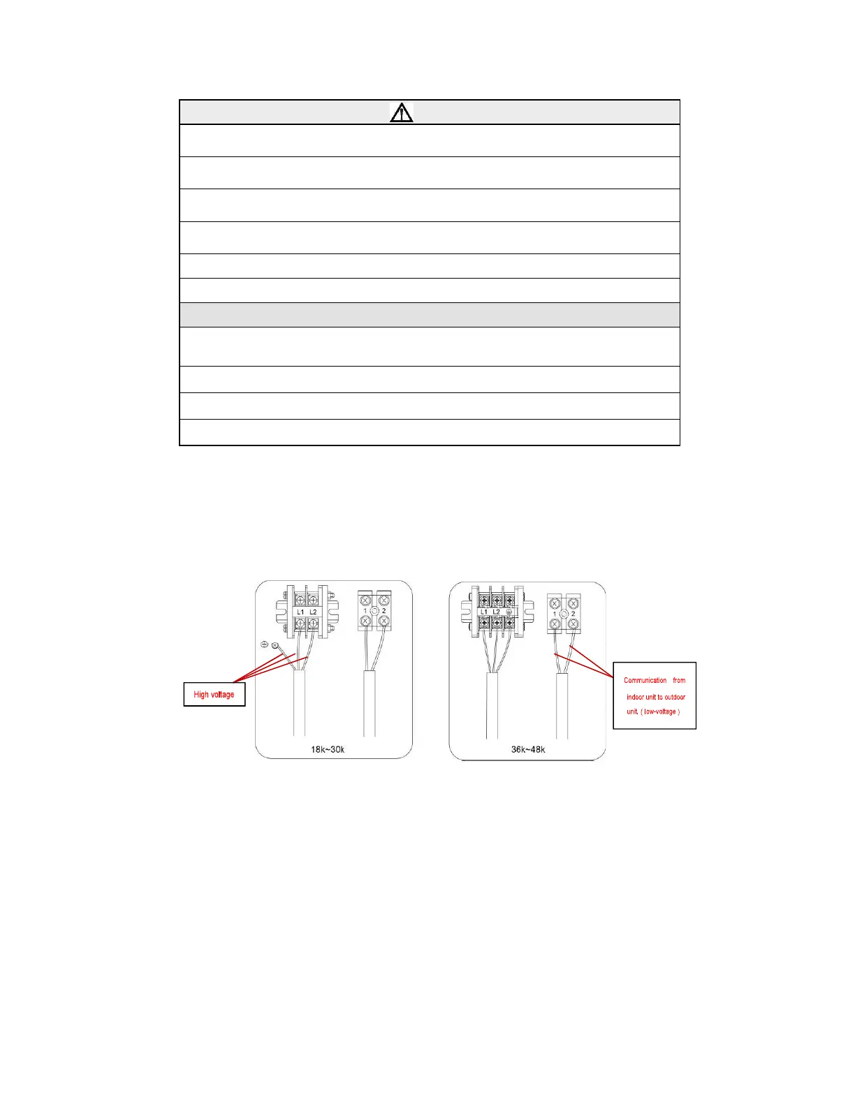
(4) Connect the indoor unit power supply and communication cable properly based on the
corresponding marks as shown in Fig. 4.39.
(5) Ground both the indoor and outdoor units by attaching a ground wire.
(6) Unit shall be grounded in compliance with the applicable local, state and national codes.
NOTICE!
(1) The high voltage power cable and the wire of the fresh air valve (not standard on this
model) are high-voltage, while the communication cable and connection wire of the wired
controller are low-voltage. They should run separately to avoid electromagnetic interference.
(2) Do not bundle the connection wire of the wired controller and the communication cord
together, or arrange them in parallel, otherwise improper operation would occur.
(3) If the indoor unit communication cable (to the outdoor unit) and power supply are improperly
wired, the air conditioner may be damaged.
(4) Connect the indoor unit power supply and communication cable properly based on the
corresponding marks as shown in Fig. 4.39.
Electric wiring of outdoor unit
Note:
When connecting the power supply cord, make sure that the phase of the power supply
matches with the exact terminal board. If not, the compressor will run improperly.
Remove the big handle (18~30K) /front board (36~48K) of the outdoor unit and insert the end of the
communication cord and the power cable into the terminal board.
Single phase:
Fig. 4.42
 Loading...