Do you have a question about the Trane SFHJ090-162 and is the answer not in the manual?
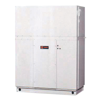
Commercial Single-Zone Rooftop Air Conditioners with CV, VAV, SZVAV, or RR Controls.
Ensures safe installation, preventing fire and electrocution hazards by following NEC and local codes.
Mandatory use of PPE for protection against electrical, mechanical, and chemical hazards.
Addresses the impact of chemicals on the ozone layer and promotes responsible refrigerant handling.
Highlights the importance of technician certification and compliance with environmental regulations.
Check nameplate, power supply, and inspect for shipping damage and material shortages.
Precautions to prevent condensate formation in electrical compartments and motors during storage.
Details minimum operating and service clearances for single or multiple unit installations.
Details information found on the unit nameplates, including model, serial, and electrical data.
Provides an alphabetically listed definition of acronyms and abbreviations used in the manual.
Describes the standard features of Trane commercial single-zone rooftop air conditioners.
Explains how the HI module allows operator adjustment of parameters and status display.
Initiates specified functions like space pressurization, exhaust, and purge control.
Details the functions of various sensors and input devices used in CV and VAV applications.
Explains compressor control and protection schemes functioning identically to traditional units.
Provides guidelines for installing roof curbs and connecting ductwork for proper unit fit-up.
Details the location for electrical entrance and recommendations for pitch pocket installation.
Step-by-step procedure for converting horizontal ductwork from the right to the left side.
Safety warning regarding proper lifting equipment rating for unit weight.
Procedure for assembling three-piece units, including rigging and securing sections.
Procedure for assembling two-piece units, including rigging and securing sections.
Instructions for connecting refrigerant tubing for one-piece and multi-piece air-cooled units.
Instructions for connecting refrigerant tubing for evaporative condenser units.
Procedure for connecting electric heat power and control wires.
Guidelines for making power and control wire connections to the unit.
Checklists for setting the unit on the curb, connecting drain lines, and removing shipping hardware.
Verifies power supply compliance and proper grounding of the unit.
Guidance for completing field wiring connections for various control types.
Ensures proper gas supply line installation, sealing, and pressure.
Instructions for routing water piping, installing the modulating valve, and actuator wiring.
Instructions for routing steam piping, installing the modulating valve, and vacuum breaker.
Steps for installing O/A pressure sensor and pneumatic tubing for VAV units.
Details on connecting evaporator drain lines and the necessity of condensate traps.
Describes the operational sequences for cooling, heating, and ventilation modes.
Details the staging of compressors and supply fan speed based on cooling demand.
Explains operation at low ambient temperatures, including LPC bypass and alternate control.
Describes the sequence for evaporative condensers, including sump fill and head pressure control.
Explains how the energy recovery wheel operates in cooling and heating modes.
Details the sequence for two-stage and modulating gas furnaces.
Describes the operation of electric heat stages for CV and VAV units.
Explains how the system controls humidity using reheat and compressor staging.
Details the operation of DCV based on CO2 levels and TRAQ™ sensor input.
Procedures for starting compressors, including verifying rotation and oil levels.
Steps for charging the system with refrigerant, including superheat and subcooling measurements.
Specific startup procedures for evaporative condensers, including water connections and shipping bracket removal.
Explains the importance of proper expansion valve adjustment for system reliability.
Procedure for measuring superheat to ensure accurate system operation.
Guidance for charging the system by subcooling, considering ambient conditions.
Startup procedures for electric, steam, and hot water heating systems.
Procedures for starting gas furnaces, including air/fuel mixture and flame adjustment.
Final checks and setup procedures before leaving the unit for operation.
Presents supply fan performance curves for various CFM and tonnage configurations.
Provides wet and dry airside pressure drop data for standard evaporator coils.
Contains performance curves for exhaust fans under different CFM and damper conditions.
Provides performance curves for return fans under different CFM conditions.
Instructions for adjusting economizer dampers for proper airflow and closure.
Details the operation and linkage of outside and return air dampers.
Procedure to adjust outside air damper travel for accurate airflow readings.
Procedure to adjust return damper actuators for proper positioning.
Describes the function and operation of the energy recovery wheel section.
Steps for starting up the energy recovery wheel, including segment and belt checks.
Procedure for safely removing energy recovery wheel segments.
Information on the galvanized steel filters used to protect the energy wheel section.
Details control settings and time delays for various furnace and airflow components.
Routine checks for filters, coils, fans, and dampers during the cooling season.
Maintenance checks for heating season, including inspection of filters and heat exchanger.
Procedure for cleaning evaporator, reheat, and microchannel condenser coils.
Guidelines for cleaning evaporative condenser coils and sump water management.
Procedure for replacing scroll compressors, including oil and refrigerant handling.
Instructions for verifying and programming VFD parameters for optimal operation.
| Brand | Trane |
|---|---|
| Model | SFHJ090-162 |
| Category | Air Conditioner |
| Language | English |