RLC-SVX07A-EN 65
Installation - Electrical
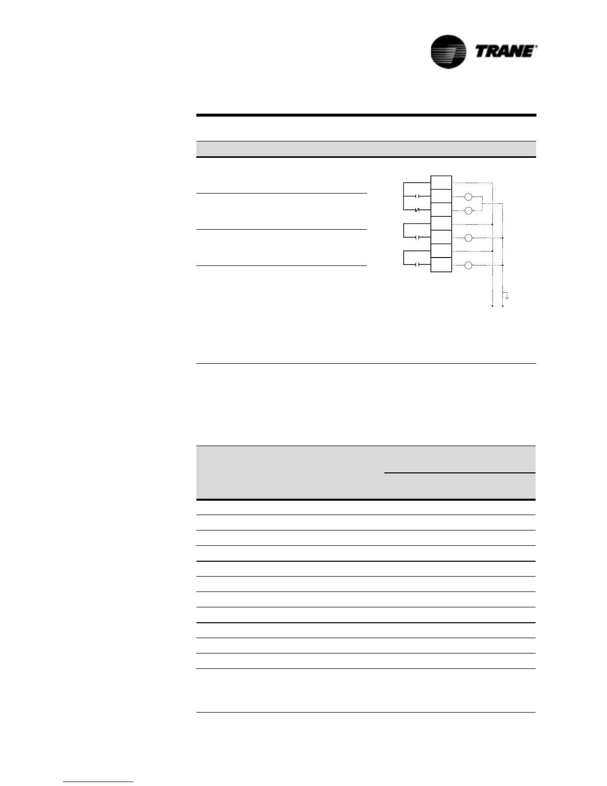
To install the available remote running and alarm indication, the installer must
provide leads 525 thru 531 from the panel to the proper terminals of terminal
strip 1U1TB4 on the UCM. Refer to the Section on “Unit Wiring” and the field
diagrams which are shipped with the unit.
Table 19 Alarm/Running/Maximum Capacity Relay Output Configurations
Relay Output Configuration Contact Outputs
1: RLY 1
RLY 2
RLY 3
= Alarm
= Compressor Running
= Maximum Capacity
2: RLY 1
RLY 2
RLY 3
= Circuit 1 Alarm
= Circuit 2 Alarm
= Maximum Capacity
3: RLY 1
RLY 2
RLY 3
= Alarm
= Circuit 1 Running
= Circuit 2 Running
Table 20 Alarm/Running/Maximum Capacity Menu Settings
Programmable
Relay Setup Setting
(Service Setting Menu)
Relays Output
Configuration
Ta b l e 1 9
Diagnostics that the Alarm
Relay(s) is Active
MMR/
CMR diag.
MAR/
CAR diag.
IFW
11YESNONO
21YESYESNO
3 1 YES YES YES
41YESNOYES
52YESNONO
62YESYESNO
7 2 YES YES YES
82YESNOYES
93YESNONO
10 3 YES YES NO
11 3 YES YES YES
Notes:
MMR = Machine Manual Reset
CMR = Circuit Manual Reset
MAR = Machine Auto Reset
CAR = Circuit Auto Reset
IFW = Informational Warnings
7%8
5HOD\
5HOD\
5HOD\
.
.
.
&XVWRPHUSURYLGHG
9$&SRZHU
0D[IXVHVL]H
DPSV
+
1
 Loading...


