RLC-SVX07A-EN 75
Installation - Electrical
Connect leads from 5RT3 to terminals 1U1 TB1-1 and TB-2 wiring to and from
the remote sensor must be made with shielded, twisted-pair conductors. Be
sure to ground the shielding only at the UCM. Apply tape to the sensor end of
the shielding to prevent it from contacting any surface.
WARNING
Hazardous Voltage w/Capacitors!
Disconnect all electric power, including remote disconnects
before servicing. Follow proper lockout/tagout procedures to
ensure the power cannot be inadvertently energized. For variable
frequency drives or other energy storing components provided by
Trane or others, refer to the appropriate manufacturer’s literature
for allowable waiting periods for discharge of capacitors. Verify
with an appropriate voltmeter that all capacitors have discharged.
Failure to disconnect power and discharge capacitors before
servicing could result in death or serious injury.
Note: For additional information regarding the safe discharge of
capacitors, see PROD-SVB06A-EN or PROD-SVB06A-FR
CAUTION
Use Copper Conductors Only!
Unit terminals are not designed to accept other types of
conductors. Failure to use copper conductors may result in
equipment damage.
Optional Bidirectional Communications Link (BCL)
This option allows the Clear Language Display in the control panel on RTWA
and RTUA units to exchange information (eg. operating setpoints and Auto/
Standby commands) with a higher level control device, such as a Tracer, a
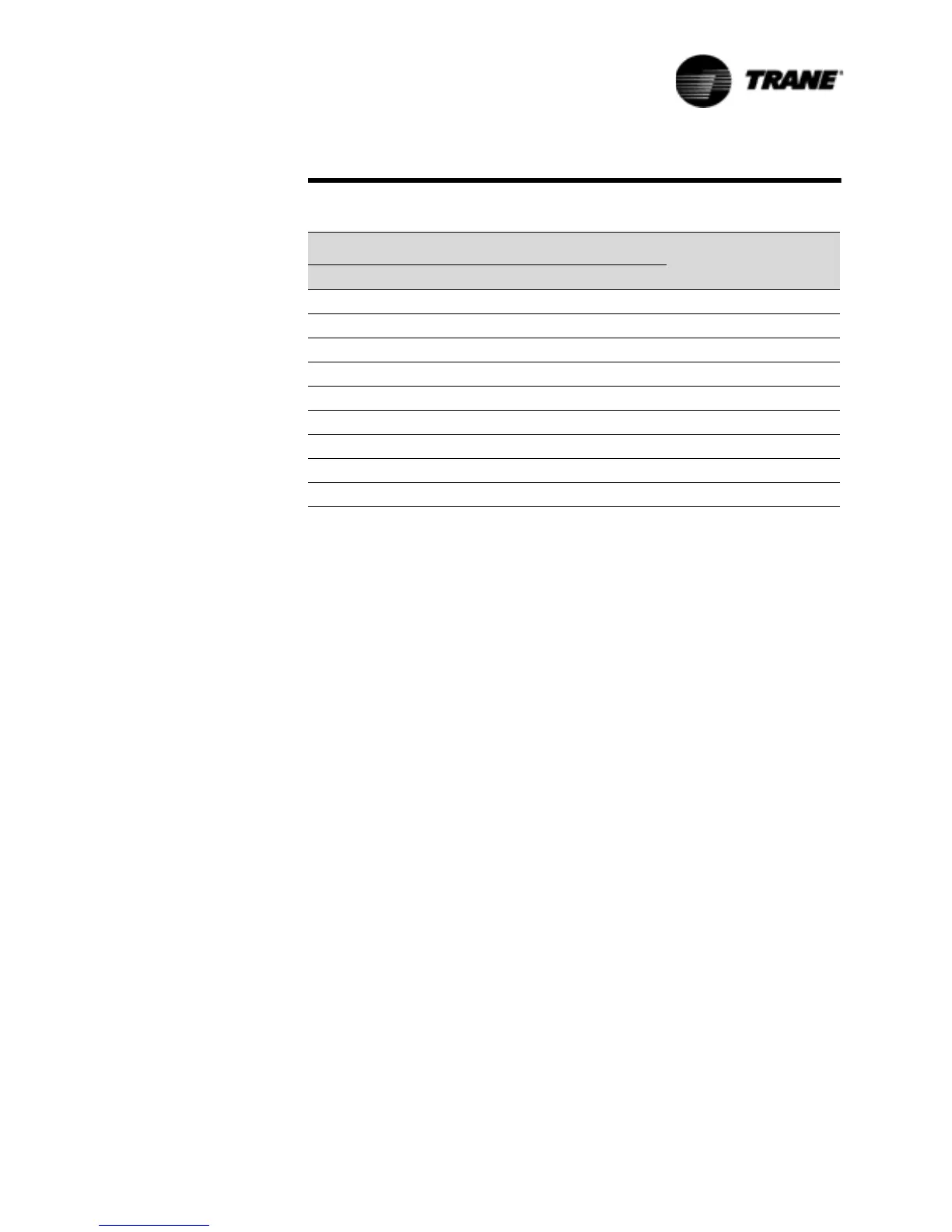
Table 23 Input Values Vs. External Current Limit Setpoint
Inputs
Resulting Chilled
Water Setpoint (%RLA)Resistance (Ohms) Current (ma) Voltage (Vdc)
49000 4.0 2.0 40
29000 6.0 3.0 50
19000 8.0 4.0 60
13000 10.0 5.0 70
9000 12.0 6.0 80
6143 14.0 7.0 90
4010 16.0 8.0 100
2333 18.0 9.0 110
1000 20.0 10.0 120
 Loading...


