74 RLC-SVX07A-EN
Installation - Electrical
Sensor Connections from Non-RTCA Unit to RTWA
If the sensor leads are not long enough to reach the desired sensor termi-
nation point on the RTUA, follow the procedures below:
1. Cut the sensor leads off, 6" from the sensors.
2. Butt-splice the sensor leads to a shielded, twistedpair cable conductor
(Belden 8760 or equivalent).
3. Slide one piece of the shrink tubing provided over the spliced area.
4. Apply heat to the spliced area until the tubing shrinks, making a weather-
proof seal.
CAUTION:
Control Malfunctions!
To prevent control malfunctions, do not run low voltage wiring
(30V or less) in conduit with higher voltage circuits.
Outdoor Air Temperature Sensor
This sensor is used for low ambient lockout and chilled water reset by outdoor
air. It ships with all RTCA units and is optional on the RTUA and RTWA units.
Remove the sensor from its shipping location in the control panel and install it
in the fresh air intake or on the north wall of the building. Protect the sensor
from direct sunlight and shelter it from the elements (RTWA only).
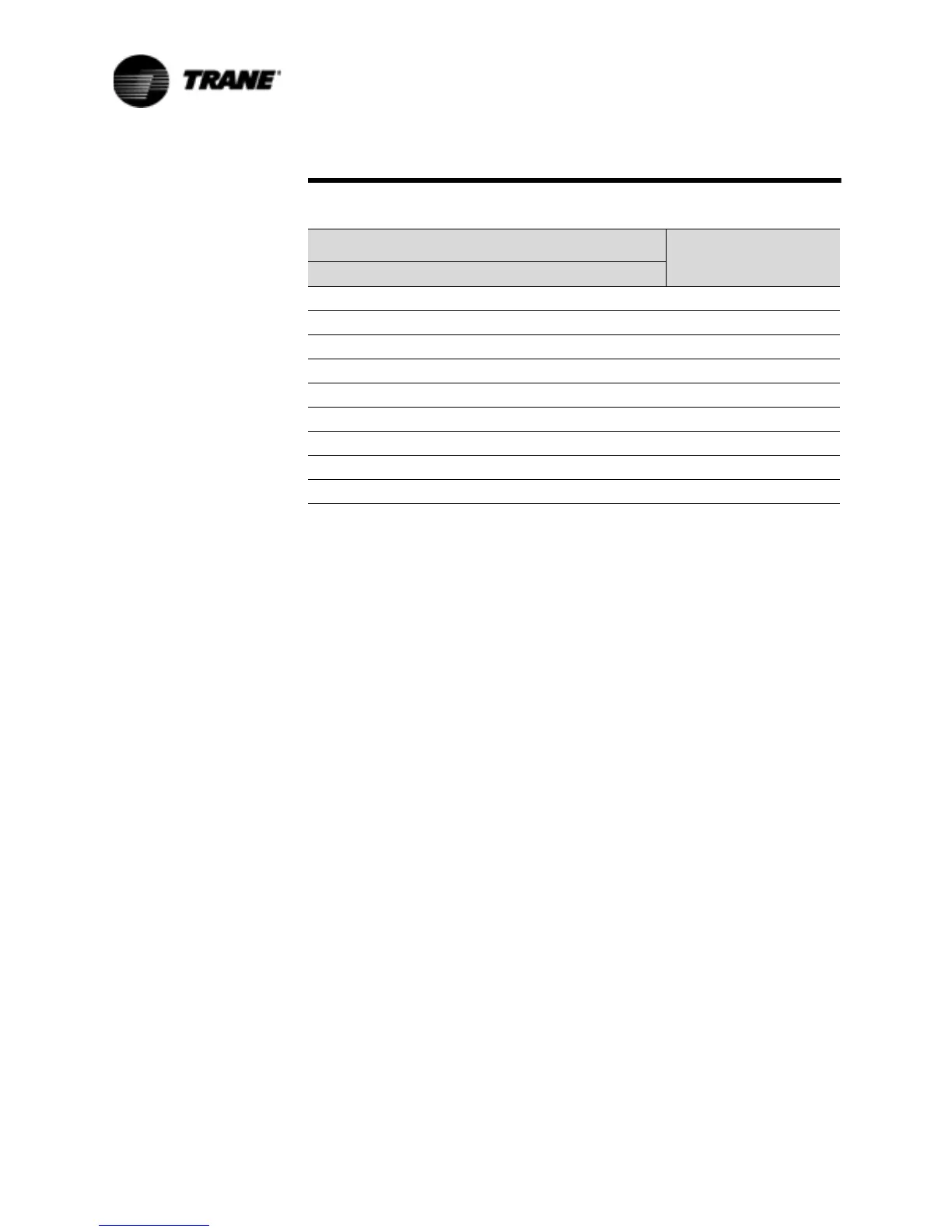
Table 22 Input Values Vs. External Current Limit Setpoint
Inputs
Resulting Chilled
Water Setpoint (%RLA)Resistance (Ohms) Current (ma) Voltage (Vdc)
49000 4.0 2.0 40
29000 6.0 3.0 50
19000 8.0 4.0 60
13000 10.0 5.0 70
9000 12.0 6.0 80
6143 14.0 7.0 90
4010 16.0 8.0 100
2333 18.0 9.0 110
1000 20.0 10.0 120
 Loading...


