RLC-SVX07A-EN 73
Installation - Electrical
isolated or “floating” with respect to the UCM chassis ground. Refer to the
Section “Unit Wiring”.
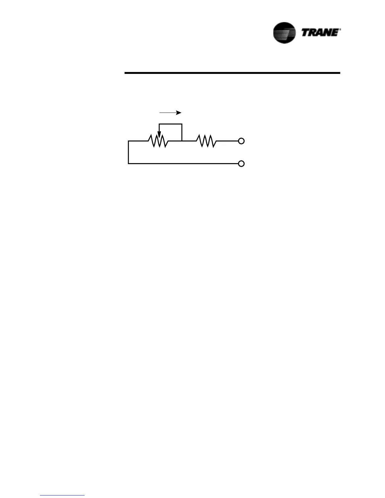
If the potentiometer is to be remotely mounted, it and the resistor must be
connected to the UCM prior to mounting. Then, with the Clear Language
Display showing “Active Current Limit Setpoint” (Chiller Report Menu), the
Clear Language Display can be used to calibrate the positions of the potenti-
ometer to correspond with the desired settings for the current limits. External
resistor input values for various current limit setpoints are shown in Tab le 28.
4. VDC Voltage Source Input
Set DIP Switch SW1-2 of Options Module 1U2 to “OFF”. Connect the voltage
source to terminals TB17 (+) and TB1-8 (-) of Options Module 1U2. CLS is
now based on the following equation:
CL Setpoint% = (VDC x 10) + 20
Sample values for CLS vs. VDC signals are shown in Table 21.
5. 4-20 mA Current Source Input
Set DIP Switch SW1-2 of Options Module 1U2 to “ON”. Connect the current
source to terminals T131-7 (+) and TB1-8 (-) of Options Module 1U2. CLS is
now based on the following equation:
CL Setpoint% _ (mA x 5) + 20
Sample values for CLS vs. mA signals are shown in Table 22.
NOTE: The negative terminal TB1-8 is referenced to the UCM chassis
ground. To assure correct operation, 2-10 VDC or 4-20 mA signals must be
isolated or “floating” with respect to the UCM chassis ground. Refer to the
Section “Unit Wiring”.
Figure 31 Resistor and Potentiometer Arrangement for External Current
Limit Setpoint
Minimum setpoint =
40% (2.0 VDC input)
Maximum setpoint =
120% (10.0 VDC input)
Maximum continuous input voltage = 15 VDC
Input impedance (SW1-1 on)
(SW1-2 off)
= 40.1 Kohms
Minimum setpoint =
40% (0 mA)
Maximum setpoint =
120% (20.0 mA)
Maximum continuous input voltage =
30 mA
Input impedance
(SW1-2 on)
= 499 ohms
7%
0RGXOH8
7%
0RGXOH8
&&:
2KPVî:
.2KP/RJ&&:3RWHQWLRPHWHU
 Loading...


