RLC-SVX07A-EN 71
Installation - Electrical
Connect leads 501 and 502 from 5K20 to the proper terminals IU2TB1-1 and -
2, as shown in Section "Unit Wiring on Page" 155. Refer to the field diagrams
which are shipped with the unit.
Silver or gold-plated contacts are recommended. These customer furnished
contacts must be compatible with 12 VDC, 45 mA resistive load.
External Chilled Water Setpoint: Remote Resistor/Potentiometer,
Voltage Source 2-10 VDC, or Current Source 4-20 mA
This option allows the external setting of the Chilled Water Setpoint,
independent of the Front Panel Chilled Water Setpoint, by one of three
means:
1. A remote resistor/potentiometer input (fixed or adjustable)
2. An isolated voltage input 2-10 VDC
3. An isolated current loop input 4-20 mA
To enable external setpoint operation, External Chilled Water Setpoint
(Operator Setting Menu) should be set to “E” using the Clear Language
Display
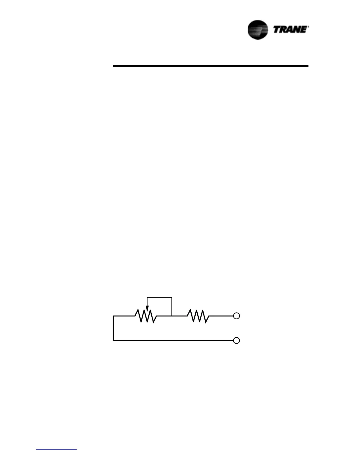
1. Remote Resistor/Potentiometer Input (fixed or adjustable)
Connect the remote resistor and/or potentiometer to terminals TB1-4 and
TB1-5 of Options Module 1U2, as shown in Figure 30.
For units with 40 F to 60 F LCWS range, a field furnished 25 Kohm linear
taper potentiometer (±10%) and a fixed 5.6 Kohm (±10%) 1/4 Watt resistor
should be used.
For units with 20 F to 39 F LCWS range, a field furnished 25 Kohm linear
taper potentiometer (±10%) and a fixed 15 Kohm (±10%) 1/4 Watt resistor
should be used.
If the potentiometer is to be remotely mounted, it and the resistor must be
connected to the UCM prior to mounting. Then, with the Clear Language
Display showing “Active Chilled Water Setpoint” (Chiller Report Menu), the
Clear Language Display can be used to calibrate the positions of the potenti-
ometer to correspond with the desired settings for the leaving water temper-
ature. External resistor input values for various chilled water setpoints are
shown in Table 21.
Figure 30 Resistor and Potentiometer
Arrangement for External Chilled Water Setpoint
3RWHQWLRPHWHU 5HVLVWRU
7%
0RGXOH8
7%
0RGXOH8
 Loading...


