10
ACC-SVN316A-EN
Installation
WARNING
Hazardous Voltage!
Failure to disconnect power before servicing could
result in death or serious injury.
Disconnect all electric power, including remote
disconnects before servicing. Follow proper lockout/
tagout procedures to ensure the power can not be
inadvertently energized. Verify that no power is
present with a voltmeter.
Component Installation
Follow the instructions on the installation drawing
(17540309) to install these components:
• Head pressure controller(s)
• 24V Transformer
• Temperature switch(es) and cover(s)
• Thermistor(s)
• Pressure transducer(s)
Note: Pressure transducers are to be installed on the
refrigerant discharge line(s). The harness provided
will reach up to 20 feet from the CA unit control box.
Wiring
Follow the instructions on the installation drawing
(17540309) to install these harnesses:
• Controls power distribution harness
• Power harness(es)
• Controls harness(es)
• Temperature switch harness(es)
• Pressure transducer harness(es)
Note: Refer to unit wiring diagrams that shipped with the
unit and low ambient field installation kit, if
necessary.
Temperature Switch Setpoint
On units that include the temperature switches (1S30 and
1S31), these should be adjusted to 65°F after installation.
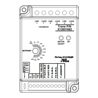
Head Pressure Controller
Setpoint
The pressure setpoint should be adjusted to 230 psig
initially.
• When the ambient temperature is above 50°F, the
condenser fan motor will be energized continuously.
• When the ambient temperature is below 50°F, the
pressure sensor measurement is used to switch the
condenser fan motor on or off.
• When the measured pressure is 15 psi below the set
pressure the condenser fan motor will be turned off.
• When the measured pressure is 15 psi above the set
pressure, the condenser fan motor will be turned on.
Notes:
• The pressure setting is adjustable from 35-465
psig
• The “Heat Pump” jumper should be placed in
the N.O. position
Figure 8. CA Low Ambient head pressure controller