6
ACC-SVN316A-EN
Installation
WARNING
Hazardous Voltage!
Failure to disconnect power before servicing could
result in death or serious injury.
Disconnect all electric power, including remote
disconnects before servicing. Follow proper lockout/
tagout procedures to ensure the power can not be
inadvertently energized. Verify that no power is
present with a voltmeter.
Component Installation
Follow the instructions on the installation drawing
(17540302) to install these components:
1. Mount actuator to damper assembly (see drawing
43567151 included in kit).
2. Mount damper assembly with actuator to roof.
Notes: Before installing the damper assembly with the
actuator, confirm the location is
• Not subject to escaping gas or other explosive
vapors that could accidentally be ignited by a
spark from the actuator or the attached parts.
• Free from acid fumes or other deteriorating
vapors that could attack the metal parts.
3. 24V transformer
4. Dual analog LLID
5. Communication cable to the LLID
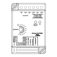
Wiring
Follow the instructions on the installation drawing
(17540302) to install these harnesses:
• Controls power distribution harness
• Control box harness
• Raceway harness(es)
Note: Refer to unit wiring diagrams that shipped with the
unit, if necessary.
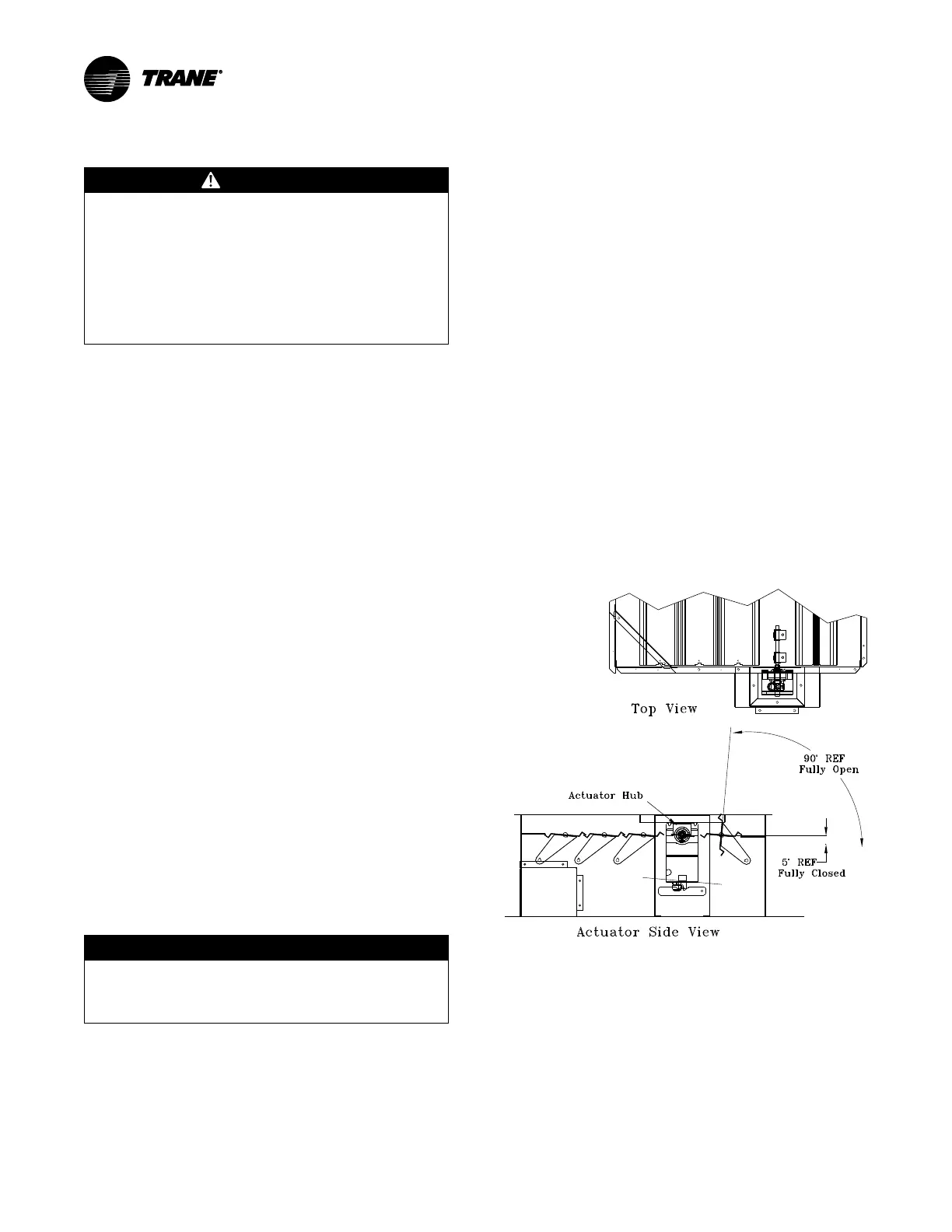
Actuator Setup
NOTICE
Actuator Damage!
Do not depress actuator clutch while actuator is
energized as it could result in actuator damage.
The actuator should be in the full clockwise (closed)
position. To align the actuator hub in the correct fully closed
position, refer to Figure 1, p. 6 and follow the steps below.
1. With the actuator clamp loose, depress the actuator
clutch button on the lower left side of the actuator and
rotate the hub clockwise to the fully closed position.
2. Holding the low ambient dampers in the fully closed
position, tighten the actuator clamp.
3. Set the direction switch on the actuator to 1 for the
Belimo actuator, or 10...2V for the Honeywell (switch
rotated to the fully clockwise position).
4. Install the actuator cover (assembled earlier) on the
damper assembly by removing the center damper
guard screw and sliding the top of the cover between
the grill and sheetmetal flange. Reinstall the grill screw
and use 1/4-20 x 1/2-inch screws for the remaining
three holes. .
5. Inspect the damper blades for proper alignment and
operation. Dampers should be in the closed position
during the Off cycle. If adjustment is required, repeat
steps 1-4.
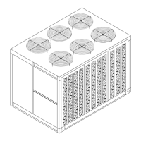
Figure 1. Damper actuator and blade alignment