17
Installation (Continued)
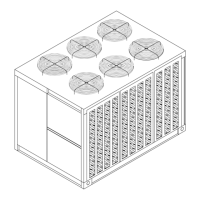
Figure 3-4
Typical Spring Isolator Selection & Location
Fin Spring Isolator Part Number @ Mounting Location
Unit Figure Mat’l. Location 1 2345678
RAUC-C80 3 AL CP-1-32 CP-1-28 CP-1-32 CP-1-28 CP-1-32 CP-1-28 CP-1-32 CP-1-28
CU CP-2-27 CP-1-28 CP-1-32 CP-1-28 CP-1-32 CP-1-28 CP-1-32 CP-1-28
RAUC-D10 3 AL CP-2-27 CP-1-31 CP-2-27 CP-1-31 CP-2-27 CP-1-31 CP-2-27 CP-1-28
CU CP-2-28 CP-1-31 CP-2-28 CP-1-31 CP-2-28 CP-1-31 CP-2-28 CP-1-31
RAUC-D12 3 AL CP-2-28 CP-1-31 CP-2-28 CP-1-31 CP-2-28 CP-1-31 CP-2-27 CP-1-31
CU CP-2-28 CP-1-32 CP-2-28 CP-1-32 CP-2-28 CP-1-32 CP-2-28 CP-1-32
Note:
1. Mountin
locations correlate with those shown in point loadin
illustration.
2. The spring number is marked on the outside of the spring housing, i.e. CP-1-27 is marked 27.
If the isolator is color coded, there is a painted mark on each spring as follows;
CP-2-27 = one orange mark CP-1-31 = two yellow marks
CP-1-28/CP-2-28 = one
reen mar
CP-1-32 = one white mark
3. Refer to the "Spring Isolator" section, step 4, for proper clearance.
Leveling the Unit
Before tightening the mounting bolts, level the unit carefully.
Use the unit base rail as a reference. Level the unit to within
1/4 inch over its entire length. Use shims if non-adjustable
isolators (neoprene) are used.
If adjustable isolators (spring) are used, ensure that the
proper isolator housing clearance is maintained while level-
ing the unit. Isolators are identified by color and/or an isola-
tor part number. Shims under the isolators may be required
if the unit can not be leveled using the isolator leveling bolt.
Shipping Fasteners
Compressor Shipping Hardware
Figure 3-5 illustrates the location of each tiedown bolt and
rubber isolator bolt for the compressor assembly in each
circuit. Refer to the illustration and the following discussion
to locate and remove the fasteners.
Three Manifolded Compressors
Each manifolded compressor assembly is rigidly bolted to a
mounting rail assembly. The rail assembly sets on six (6)
rubber isolators. The assembly is held in place by four (4)
shipping “Tiedown” bolts. To remove the shipping hardware,
follow the procedures below:
1. At each “Tiedown” location (2 front and 2 rear), remove
and discard the tiedown bolt and the slotted shipping
 Loading...