6
RAU-SVX01G-GB
Installation
Table 1 –
Dimensions of recommended slings and swing-bar:
190 260 300 350 400 450 500 600 700 800
A (mm) 1500 1500 1500 1500 1500 1500 2400 2400 2300 2300
B (mm) 1800 1800 1800 1800 1800 1800 1800 1800 2200 2200
Weight - crated (kg) 555 625 691 869 959 985 1123 1251 1695 1754
Refrigerant lines
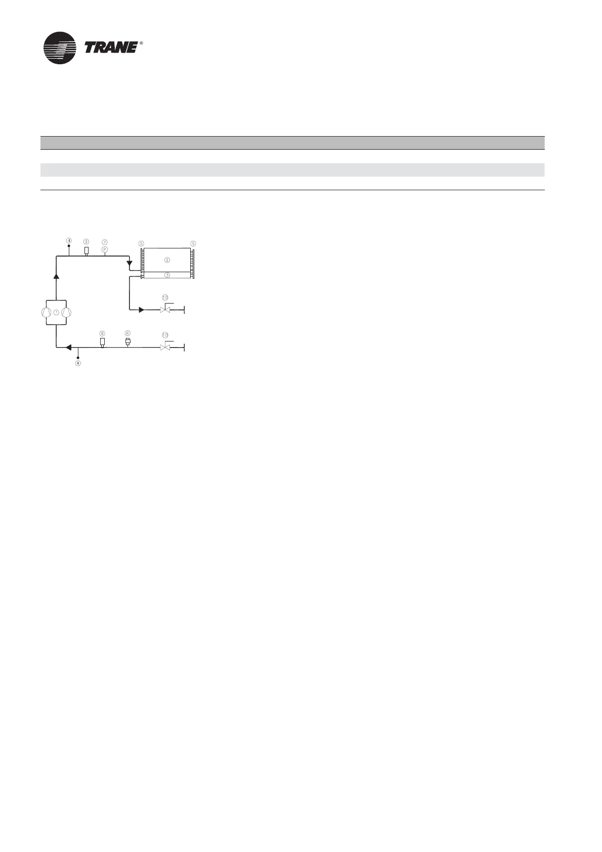
Figure 2 –
Refrigerant fl ow chart
1 = Compressor
2 = Condenser coil
3 = Subcooler coil
4 = Schraeder valve
5 = Coil header
6 = Relief valve
7 = High pressure switch
8 = Low pressure transducer
9 = High pressure transducer
10 = Stop valve
Calculating and fi xing the capacity of refrigerant lines is necessary to assure the oil return to the compressor, avoid
refrigerant phase changes and limit pressure drop.
Liquid lines
Calculate capacity of liquid line, as per the following criteria.
1. Maximum load operating conditions.
2. To avoid any evaporation risk:
– Consider the vertical risers
– Maximum pressure drop must not exceed 1 to 2°C
3. Liquid circulation speed in a 0.5 to 2m/s range.
Discharge lines
Discharge lines should be calculated to obtain the gas displacement speed in horizontal and vertical lines required to
drive compressor oil. Determine diameter of discharge lines as per the following criteria.
1. Speed above 2.5 m/s horizontally. (Consider minimum speed at minimum load).
2. Speed above 5.0 m/s vertically (Vertical risers, consider speed at minimum load).
3. Maximum speed 20 m/s.
4. Horizontal pipe run must be pitched of 1cm/m in the same direction as the refrigerant circulation.
5. An oil trap is necessary for vertical risers greater than 3m. For major elevations add an intermediate oil trap
every 5m.
6. Maximum pressure drop between 20 to 50 kPa.
7. Install a fi lter drier adapted to refrigerant capacity.
 Loading...