Controls
35RT-SVX19A-E4
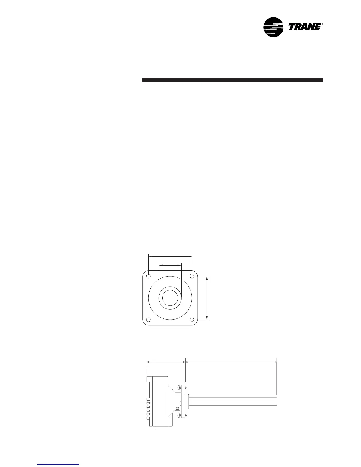
Mounting the duct-mounted CO
2
sensor
1. Select a proper location on the
duct to mount the CO
2
sensor.
2. Drill a 22-25 mm hole in the
mounting surface for sensor
insertion (Figure 13).
3. Attach the mounting plate to the
duct wall with four screws.
4. Insert the sensor through the
mounting plate, adjusting the
depth for optimal air sensing.
Figure 13 - Duct-mounted CO
2
sensor
Figure 14 - Duct-mounted CO
2
insertion depth
CO
2
sensor maintenance
This CO
2
sensor has excellent
stability and requires no
maintenance. In most environments
the recommended calibration
interval is five years. A trained
service technician can use a
portable CO
2
meter to certify sensor
calibration. If, when checking the
sensor, the reading differs too much
from the reference value, the sensor
can be recalibrated in the field. A
calibration kit, software, and
calibration gases are required. If
certified accuracy is required, the
sensor must be calibrated against
accurate and traceable calibration
gases in a laboratory. Consult Trane
BAS for further details.