RLC-SVX02G-E4
52
Installation – Electrical
The following equations apply:
XX = Out of range diagnostic
I = Input
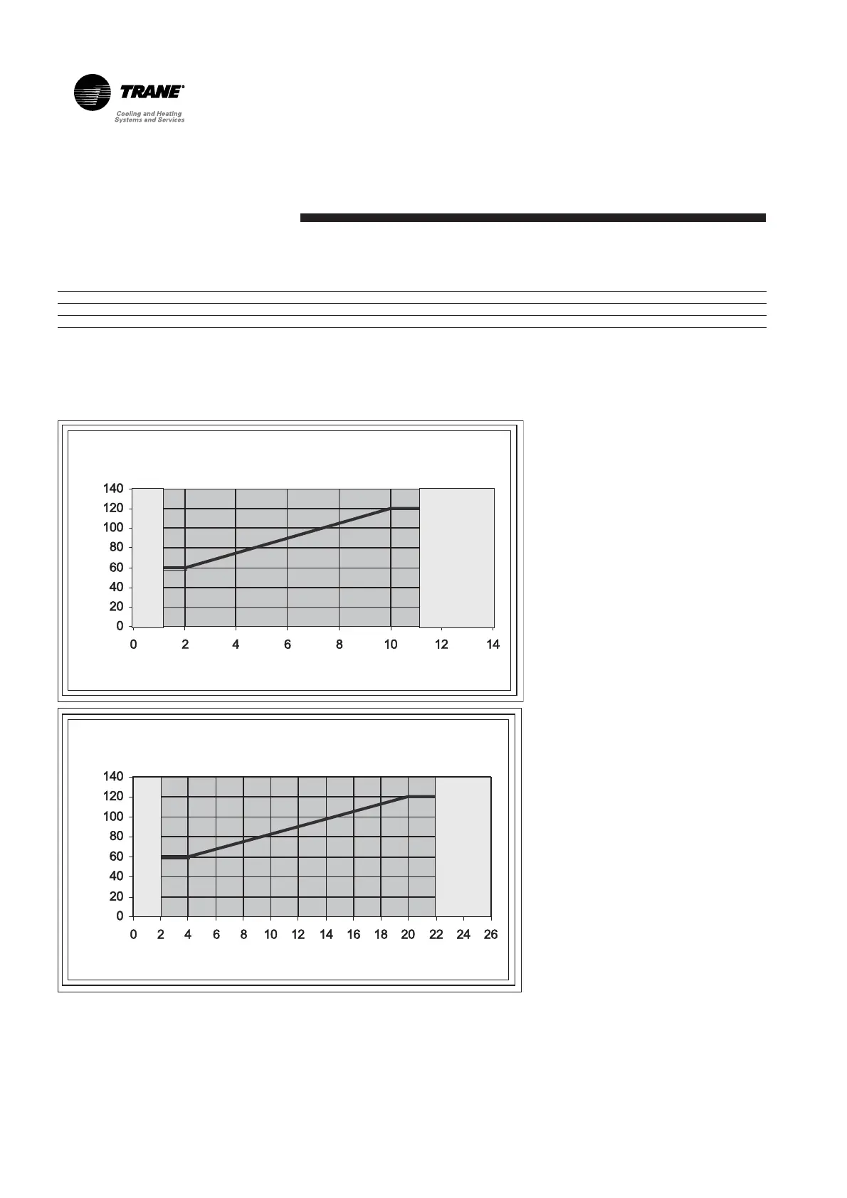
ECLS = External Current Limit
Setpoint
VDC = Volt Direct Current
mA = milliamps
ECLS -vs- Input (VDC)
ECLS -vs- Input (mA)
Input (VDC)
Input (mA)
ECLSECLS
For RTAC Units Voltage Signal Current Signal
As generated from external source Vdc=0.133*(%)-6.0 mA=0.266*(%)-12.0
As processed by Tracer CH530 % = 7.5*(VDC)+45.0 % = 3.75*(mA)+45.0
As a graph this yields the following:
For input signals beyond the 2-
10VDC or 4-20mA range, the end of
range value is used. For example, if
the customer inputs 21 mA, the
ECLS limits it self to the
corresponding 20 mA ECLS.
XX
XX
XX
XX