69
RLC-SVX02G-E4
Maintenance Procedures
Table 16 – Oil Charging Data
60-70 7.6 2.0 178 7 1.1 0.5
85 7.6 2.0 152 6 1.1 0.5
100 9.9 2.6 178 7 1.8 0.8
140 17.0 4.5 203 8 3.5 1.6
170 17.0 4.5 203 8 3.5 1.6
200 19.0 4.9 203 8 3.5 1.6
Recommendation: check the oil level in the sump using a sight glass or a manometer, attached to
charging hoses.
Proper charging of the oil system is
critical to the reliability of the
compressor and chiller. Too little oil
can cause the compressor to run hot
and inefficiently. When taken to an
extreme, low oil level may result in
instant failure of the compressor.
Too much oil will result in high oil-
circulation rates, which will foul the
condenser and evaporator
performance. This will result in
inefficient operation of the chiller.
Taken to an extreme, high oil levels
may result in erratic expansion-
valve control or shut down of the
chiller due to low evaporator-
refrigerant temperature. Too much
oil may contribute to long-term
bearing wear. Additionally,
excessive compressor wear is
probable when the compressor is
started with the oil lines dry.
Oil system consists of the following
components:
• Compressor
• Oil separator
• Discharge line with service valve
• Oil line from separator to
compressor
• Oil line drain (lowest point in
system)
• Oil cooler (option)
• Oil temperature sensor
• Oil line shutoff valve with flare
service connection
• Oil filter (internal to compressor)
with flare-fitting service
connection and schrader valve
• Oil flow-control valve (internal to
the compressor after the filter)
• Oil return line from evaporator
with shutoff valve, oil filter, and
solenoid control valve (for the
manifold compressor circuits only)
The standard oil charge for each
circuit size is shown in Table 16.
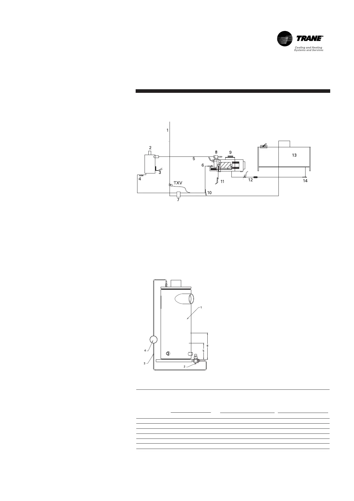
1. From Subcooler
2. Oil Separator
3. Heater
4. Oil Drain Valve
5. High-Pressure Cutout Load-
Control Solenoid
6. Oil Line Shutoff Valve Oil Filter
7. Oil Cooler (option)
8. Discharge Isolation Valve (option)
9. Compressor
10. Oil Temperature Sensor
11. Oil Pressure Transducer
12. Oil Filter
13. Evaporator
14. Oil Return Line Shutoff Valve
Figure 9 – Oil System Schematic
Figure 10 – Oil System Schematic
1. Oil separator
2. Valve
3. ¼" refrigeration hose
4. Sight glass
5. Minimum oil level
6. Maximum oil level
Circuit
Tons
liters
Oil Charge
Gallons
Approximate
sump
oil level after
running "normal"
conditions
mm
inch
Normal quantity
of oil
in refrigeration
system
(evaporator/condenser)
lb
kg