RLC-SVX02G-E4
56
Operating Principles
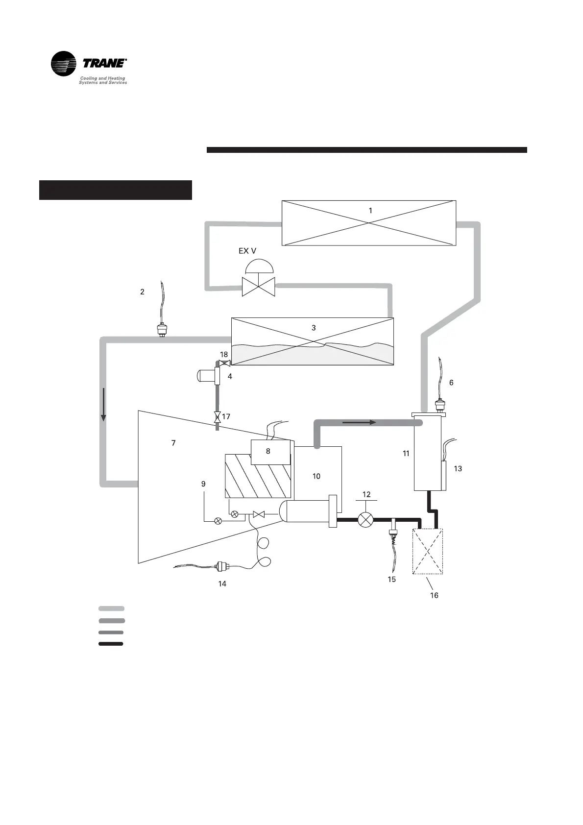
Figure 8 – RTAC Oil System
Key:
Refrigerant with small amount of oil
Refrigerant and oil mixture (refrigerant vapor and oil)
Oil recovery system (liquid refrigerant and oil)
Primary oil system
1. Condenser
2. Evaporator Refrigerant Pressure Transducer P
E
3. Evaporator
4. Evaporator Oil-Return Line Filter
6. Condenser Refrigerant Pressure Transducer P
C
7. Compressor
8. Compressor Heater
9. Bearing and Rotor Restrictors and Oil Injection
10. Internal Compressor Oil Filter
11. Oil Separator
12. Manual Service Valve
13. Oil Separator Sump Heater
14. Intermediate Oil Pressure Transducer P
I
15. Compressor Oil Temperature Sensor
16. Optional Oil Cooler
17. Solenoid valve (manifolded compressors
only)
18. Manual service valve
The RTAC units must only operate
with R-134a and Trane OIL 00048E.