Current Transformer and Current Input
RTHC-SVD01B-EN 23
Section 4 Current Transformer and Current Input
4-1. General
Each compressor motor has all three of its line currents monitored by
torroid (doughnut) current transformers. The Starter module utilizes all
of the signals and displays the phases under the compressor report.
These currents are also normalized with respect to the Rated Load
Amps of the respective compressor and thus are expressed in terms of
%(percent) RLA. The currents are “normalized” through the proper
selection of the Current Transformer and the setting of the Current
Overload Settings #1 and #2 in the Machine Configuration Menu. The
following procedure is used to determine the current overload setting
#1 and #2 in the UCP2 menu items. First determine the CT Factor:
Refer to 4-1 for the CT Rating. It should be larger than the unit name-
plate RLA. The CT Factor must be 66% or greater but no more than
100% of the name plate RLA. In some cases, more than one selection
is possible: select the CT Rating that gives the lowest CT Factor.
CT Factor(%) =
(Unit nameplate RLA)
X 100
CT Rating (from 4-1)
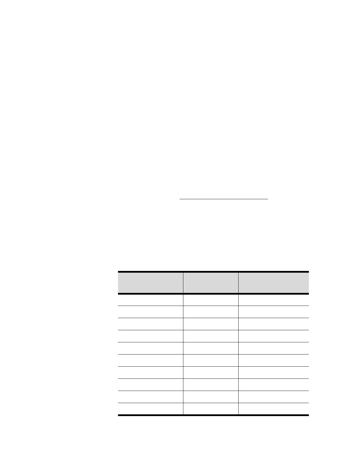
Table 4-1: Current Transformer Selection
CT Extension #
(X13580269-)
CT Rating
(Amps)
Winding Resistance
(Ohms)
01 100 A 23.5
02 150 A 35.0
03 200 A 46.0
04 275 A 67.0
05 400 A 68.0
06 500 A 84.0
07 700 A 128.0
08 1000 A 235.0
09 50 A 11.5
10 75 A 17.0