Interprocessor Communication (IPC)
RTHC-SVD01B-EN 61
12-3 a. Opens or shorts in the twisted pair IPC wiring or
connectors:
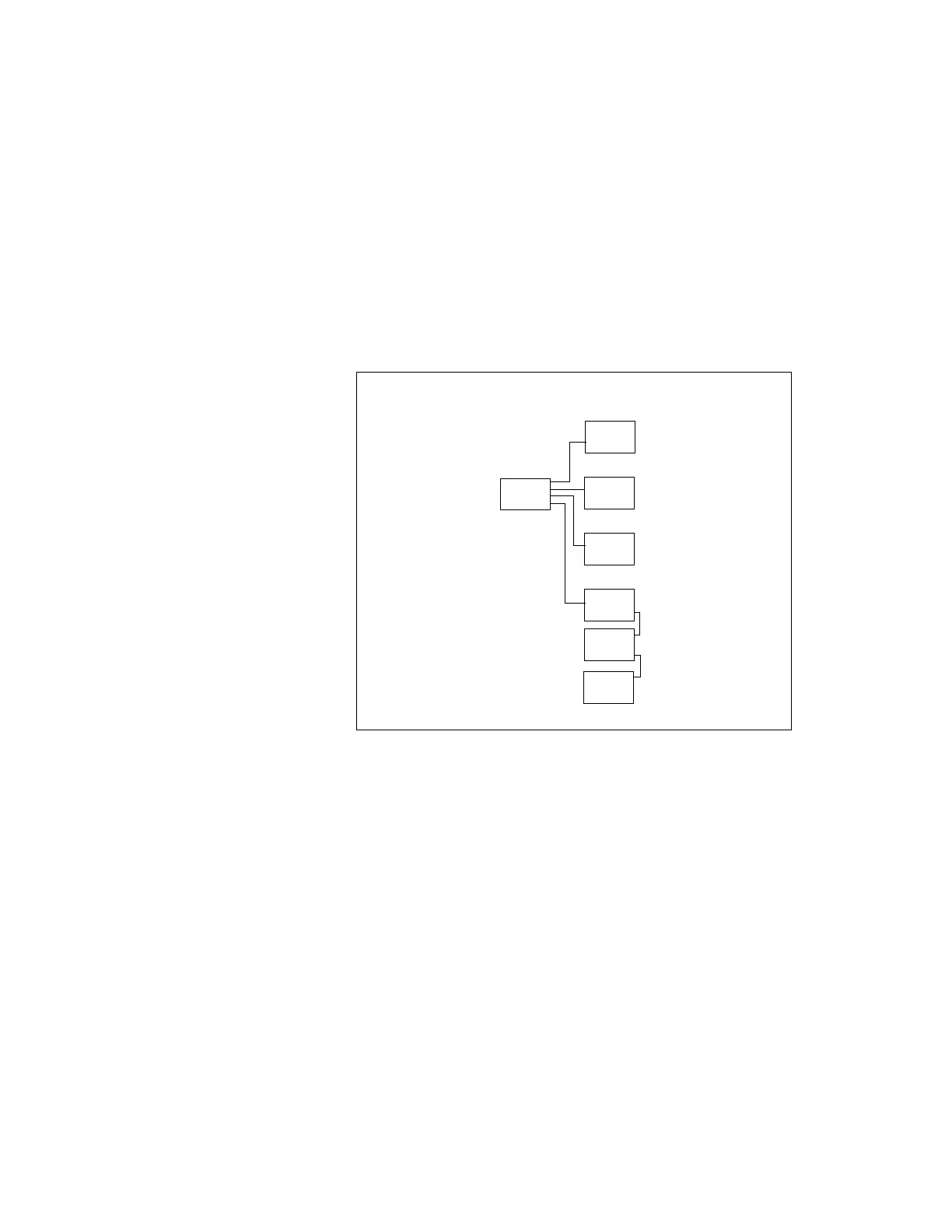
One or more modules may be affected by an open or a short in the IPC
wiring, depending on the location of the fault in the daisy chain. The
diagram below shows the daisy chain order and is helpful in the diag-
nosis of an open link.
12-3 b. Loss of power to a module:
Generally, a power loss to a particular module will only affect communi-
cations with that module. The module can usually be identified by anal-
ysis of the IPC diagnostics.
NOTE: If the CLD is blank, check power to the CLD.
Loss of power can most directly be diagnosed by measuring the 24
VAC voltage at the 4 pin J2 connector on all modules. Each module will
have between 20 and 28 VAC across J2 1-2 and J2 3-4.
Figure 12-1 IPC Daisy Chain
1U1
1U2
1U7
1U3
1U5
1U6
1U4