Module Power and Miscellaneous I/O
76 RTHC-SVD01B-EN
13-5. Starter Module (1U2)
13-5 a. Test Points
There are two test points (TP) associated with the Starter module.
They are easily read with a DC voltmeter by probing the PC board sol-
der pads found in the upper left hand corner of the module. The DC
voltages shall be within the tolerances specified below. If not replace
the module.
Do not use the aluminum module enclosure as the reference as it
has an anodized surface with insulating properties.
13-5 b. I/O Terminals
For the checkout of the I/O, refer to the Chiller Wiring Diagrams for
both high and low voltage circuits. All voltages are measured between
terminal pairs specified unless otherwise indicated. Nominal voltages
are given and may vary by +
5%. Unregulated voltages (unreg) or 115
VAC voltages may vary by +
15%.
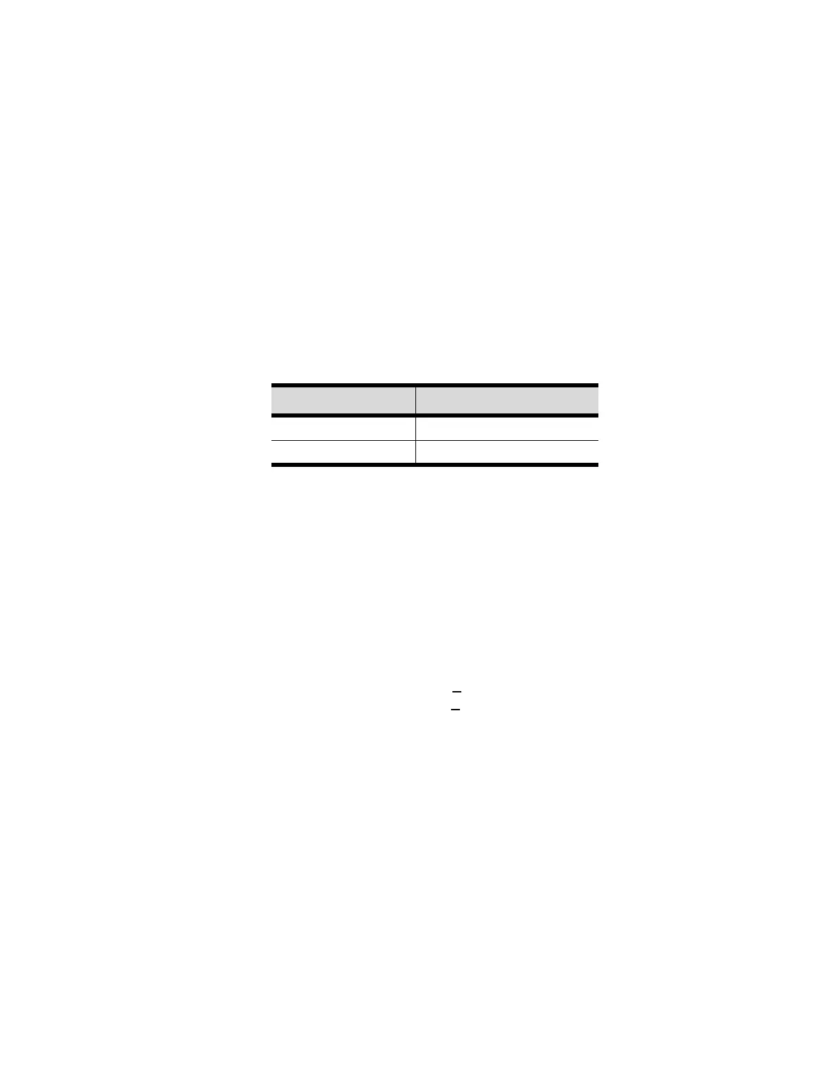
Table 13-4: Test Point Voltages for 1U2 Module
Test Point Voltage (VDC)
TP1 23 to 25
TP2 4.8 to 5.2