Quick Start, Initial Parameters
40 RLC-SVN005B-EN
Current Transformer Set-up (MX Only)
CT Switch Settings
When the starter is shipped from the factory, CT settings
are set to match CT ratios supplied with the starter. If the
MX control is changed the CT settings must be changed to
match the CT ratios for that given current rating.
To verify or change the motor current signal scaling:
• Compare the CT ratio stamped on each CT to the CT
ratio listed
on the wiring diagram supplied with the
starter to ensure the correct CTs are installed.
• Inspect the control card to ensure th
at the DIP switches
are in the correct positions for the applicable CT ratio
and the motor full-load current (FLA).
Table 2. CT switch settings
CT
Ratio
Minimum
FLA (A
rms
)
Maximum
FLA (A
rms
)
Switch 6
Position 1
Switch 6
Position 2
2640
73 128 Off Off
128 151 Off On
151 330 On Off
330 590 On On
5760
590 720 On Off
720 1280 On On
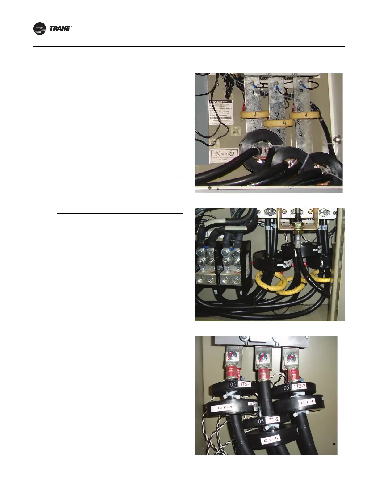
CT Polarity (MX and MX2)
CT has a polarity that must be correct for starter to
accurately measure Watts, kW Hours, Power Factor, and
for Power and TruTorque motor control functions to
operate properly.
Each CT has a dot on one side of flat surfaces. The dot,
n
ormally
white, must be facing in direction of the line.
The CT can be placed either before or after the starter. In
sp
ecific applications, like Inside Delta, the CT's must be
before the starter.
CT1 must be on Line L1 (R), CT2 must be on Line L2 (S), CT3
m
ust be
on Line L3 (T).
Figure 37. RTHB - Installation of CTs
Figure 38. RTHC - Installation of CTs
Figure 39. RTHD - Installation of CTs