EasyManua.ls Logo

Trane S8V2C100M5PC - User Manual

Trane S8V2C100M5PC
84 pages
To Next Page IconTo Next Page
Loading...
SSAAFFEETTYY WWAARRNNIINNGG
Only qualified personnel should install and service the equipment. The installation, starting up, and servicing of heating, ventilating, and air-conditioning
equipment can be hazardous and requires specific knowledge and training. Improperly installed, adjusted or altered equipment by an unqualified person
could result in death or serious injury. When working on the equipment, observe all precautions in the literature and on the tags, stickers, and labels that
are attached to the equipment.
October 2022 SS88VV22--SSVVXX000011--11AA--EENN
Link Communicating or 24 Volt Gas-Fired 2 Stage Induced
Draft Furnaces with Variable Speed Motor
UUppffllooww,, DDoowwnnffllooww,, HHoorriizzoonnttaall RRiigghhtt//LLeefftt
Two Stage
S8V2-C
S8V2A040M3PC/D
S8V2B060M4PC/D
S8V2B080M4PC/D
S8V2C080M5PC/D
S8V2C100M5PC/D
S8V2D120M5PC/D
NNoottee:: Models that have a “D” in the 12th digit designating they meet California
less than 40 ng/J (NOx) emissions requirements.
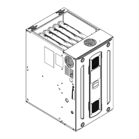
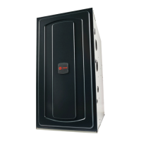
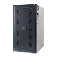
NNoottee:: Graphics in this document are for
representation only. Actual model may
differ in appearance.
TM
The Diagnostics Mobile App is available by scanning a QR code
located inside this unit or by searching for the Link Diagnostics
App in your App Store.
When using the Link Communicating protocol, the furnace must
be used with A/T HUI2360A200U thermostat and
TSYS2C60A2VVU* System Controller.
S8V2-SVX001-1A-EN
Installation, Operation, and Maintenance
Question and Answer IconNeed help?

Do you have a question about the Trane S8V2C100M5PC and is the answer not in the manual?

Trane S8V2C100M5PC Specifications

General IconGeneral
ModelS8V2C100M5PC
TypeGas Furnace
Efficiency RatingUp to 96% AFUE
Heating Capacity100, 000 BTU
Blower MotorVariable Speed
Ignition TypeHot Surface Ignition
StagesTwo-stage
EfficiencyUp to 96% AFUE
Blower Motor TypeVariable Speed ECM
Warranty10-Year Limited Parts Warranty
Fuel TypeNatural Gas

Summary

Installation, Operation, and Maintenance

Safety Section Non-Condensing Furnaces

Carbon Monoxide Poisoning from Venting Procedures

Critical steps for safe appliance operation connected to venting systems to prevent CO poisoning.

Furnace Installation Guidelines

Installation Safety Practices and Precautions

Essential safety practices and precautions for furnace installation and servicing.

Wiring Diagrams

Furnace General Installation

Furnace General Installation

Gas Valve Adjustment Procedure

Step-by-step instructions for adjusting gas valve manifold pressure for heating stages.

High Altitude Derate Procedures and Orifice Changes

Instructions and tables for adjusting furnace input rate and orifices for high altitude installations.

Air for Combustion and Ventilation Requirements

Guidelines for providing adequate combustion and ventilation air for confined and unconfined spaces.

Confined Space Ventilation Requirements

Detailed requirements for ventilation air from outdoors or inside buildings for confined spaces.

Electrical Connections and 24 V Field Wiring

Instructions for making electrical connections and a field wiring diagram for thermostats.

General Start-up and Adjustment

Control and Safety Switch Adjustment

Instructions for checking and adjusting limit switches and other safety controls.

Furnace Combustion Air Exhaust Options

Integrated Furnace Control Menu

Run Test Mode and System Status

Instructions for entering run test mode and understanding system status and error codes.

Integrated Furnace Control Display Codes

Integrated Furnace Control Error Codes

Explanations for various error codes generated by the IFC.

Integrated Furnace Control Display Codes

IFC Error Code Explanations

Detailed explanations for IFC error codes related to limits, pressure switches, and flame sensing.

Fault Code Recovery Procedures

Steps to view and clear fault codes from the Integrated Furnace Control.

Troubleshooting

Troubleshooting Flowcharts - Getting Started and E01

Flowchart for initial troubleshooting steps and diagnosis of E01 Internal Failure.

Troubleshooting Flowcharts - E2.1 and E3.1 Faults

Flowcharts for diagnosing E2.1 (Flame Sense) and E3.1 (Pressure Switch) faults.

Troubleshooting Flowcharts - E2.2, E2.3, and E3.2 Faults

Flowcharts for diagnosing E2.2 (Recycles), E2.3 (Gas Valve), and E3.2 (Pressure Switch) faults.

Troubleshooting Flowcharts - PS1 and Inducer Faults

Flowcharts for diagnosing pressure switch (PS1) and inducer motor issues.

Troubleshooting Flowcharts - PS2 and Igniter Faults

Flowcharts for diagnosing pressure switch (PS2) and igniter related faults.

Troubleshooting Flowcharts - Main Thermal Limit Fault

Flowchart for diagnosing issues related to the main thermal limit switch.

Troubleshooting Flowcharts - Reverse Airflow Limit Fault

Flowchart for diagnosing faults related to the open reverse airflow limit switch.

Troubleshooting Flowcharts - Roll-Out Limit Fault

Flowchart for diagnosing faults related to the roll-out limit switch and burner issues.

Troubleshooting Flowcharts - Flame Sense Error

Flowchart for diagnosing flame sensing errors and inlet gas screen issues.

Troubleshooting Flowcharts - Polarity and Ground Faults

Flowcharts for diagnosing polarity and ground fault errors in high voltage wiring.

Troubleshooting Flowcharts - Igniter Relay and Circuit Faults

Flowcharts for diagnosing igniter relay and circuit faults.

Troubleshooting Flowcharts - Gas Valve and High Limit Faults

Flowcharts for diagnosing external gas valve circuit and high limit relay faults.

Troubleshooting Flowcharts - Flame Sense Current

Flowchart for diagnosing low flame sense current issues and flame sensor location.

Troubleshooting Flowcharts - Gas Valve Relay and Fuse Faults

Flowcharts for diagnosing gas valve relay and fuse faults, including amp draw checks.

Troubleshooting Flowcharts - Blower Motor and File Corruption Faults

Flowcharts for diagnosing blower motor mismatch and file corruption errors.

Troubleshooting Flowcharts - Low Voltage Wiring and Motor Faults

Flowcharts for diagnosing low voltage wiring issues and serial motor faults.

Troubleshooting Flowcharts - IFC Data and Communication Errors

Flowcharts for diagnosing IFC menu data, internal communication, and orientation sensor errors.

Troubleshooting Flowcharts - Static Pressure and Return Sensor Faults

Flowcharts for diagnosing return static pressure transducer and return air thermistor faults.

Troubleshooting Flowcharts - Supply Sensor Faults

Flowchart for diagnosing supply air thermistor faults.

Sequence of Operation

Periodic Servicing Requirements

Related product manuals