18
7.3 Downflow Installation
• Downflow installation must comply with national,
state, and local codes.
• The air handlers are rated for zero clearance from
combustible materials.
STEP 1 - Prepare the location site as appropriate for
your application and per national, state, and local code
requirements.
STEP 2 - Set the unit in position.
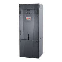
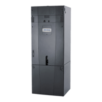
Representative Illustration
Typical Downflow Installation
Important: Ensure EEV sensor and motor wiring
are taut and wire-tied to the distributor tube to pre-
vent damage during electric heat operation.
Important: For the 5 ton air handler model, tap 5
should not be used in the downflow or horizontal
orientations. Using Tap 5 could result in water
blowing off the coil.

 Loading...


