Settings for Version I (Comfort Man-
ager), Version II and Version III (Op-
tional Touchpad Display) VariTrac
The TCI-3 board is supported by VariTrac Ver-
sion I (Comfort Manager), Version II, and Ver-
sion II (Optional Touchpad display). The TCI se-
rial Comm link must be in the same daisy chain
as the VAV box serial Comm link. The Comm
link board must be positioned for non-isolated
Com 3 or Com 4 position. Verify that the TCI-3
DIP switch settings are as shown in Table 3.
TCI-3 DIP Switch Address Settings
The DIP switch (SW1) is located on the upper
right corner of the TCI-3 board. DIP switch SW1-
1 is used to enable (ON) or disable (OFF) the op-
tional High Temperature Limit Switch binary in-
put (TB2 on the TCI-3 board). DIP switches SW1-
2 through SW1-6 are used to set the Voyager Mi-
cro Rooftop TCI-3 addresses.
Settings for Tracker/ComforTrac
The TCI-3 board is supported by Tracker/
ComforTrac Building Management Systems. The
Com Link Board must be positioned for Isolated
Com 3 communications. A maximum of 12 Voy-
ager Micro Rooftop TCI-3’s can be defined for
each Tracker/ComforTrac system.
Table 2
TCI-3 Board DIP Switch Address Settings for
Tracker/ComforTrac
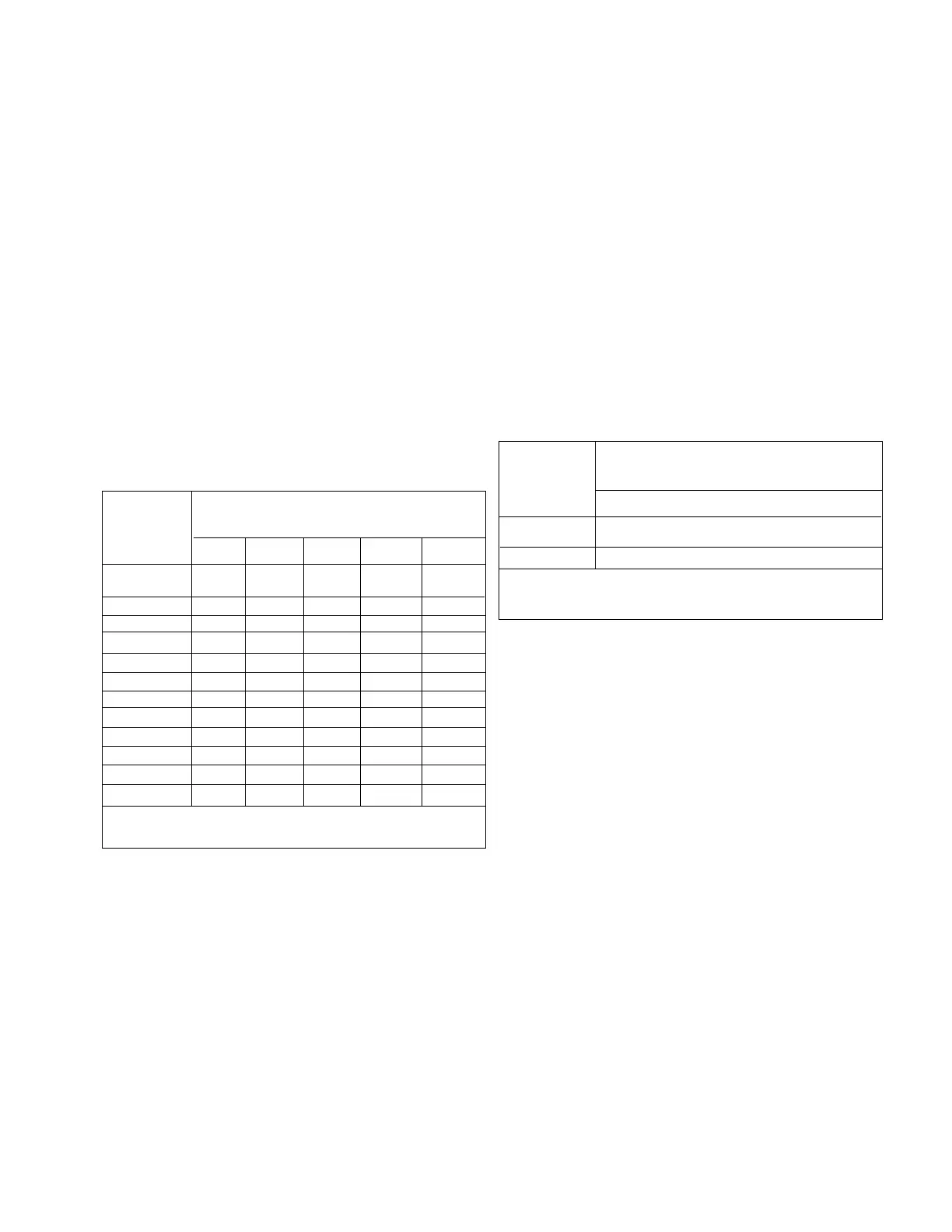
Table 3
TCI-3 Board DIP Switch Address Settings for VariTrac
TCP3 Board Address
DIP Switch Settings
Voyager
Address
Numbers
SW1, 2 SW1-3 SW1-4 SW1-5 SW1-6
OFF OFF OFF OFF OFF
OFF OFF OFF OFF ON
OFF OFF OFF ON OFF
OFF OFF OFF ON ON
OFF OFF ON OFF OFF
OFF OFF ON OFF ON
OFF OFF ON ON OFF
OFF OFF ON ON ON
OFF ON OFF OFF OFF
OFF ON OFF OFF ON
OFF ON OFF ON OFF
OFF ON OFF ON ON
01
02
03
04
05
06
07
08
09
10
11
12
SW1-1is used to enable (ON) or disable (OFF) the optional High Temperature Limit Switch binary input
(TB2 on the TCI-3 board).
Settings for Tracer 100 Series
Panels and Tracer Summit Sys-
tems
The TCI-3 board, which is mounted on the
Voyager Micro Rooftop Unit Control Panel,
is supported by Tracer 100 Series panels
using Version 12 software and Tracer Sum-
mit systems.
Tracer Version 12 software introduced a
new system addressing scheme which al-
lows an operator to configure a maximum of
64 Tracer addresses out of an available
range of 1 through 81.
Tracer Version 13 is the latest software ver-
sion that has a maximum of 32 Voyager Mi-
cro Rooftop TCI-3’s that can be defined for
each Tracer 100 and Tracer 100i. A maxi-
mum of 20 Voyager Micro Rooftop TCI-3’s
can be defined for each Tracer L and Tracer
Monitor.
Note: The amount of TCI-3’s supported
by Tracers is dependent on the soft-
ware version being used. Refer to the
Tracer 100 Series literature for specific
quantities.
The range of Tracer address numbers that
may be defined for Voyager Micro Rooftop
TCI-3’s is 50 through 81. To configure an ad-
dress for a Voyager Micro Rooftop unit, assign
it’s point number (i.e. 30-01, 30-02, 30-03,
etc.) to a Tracer address within the acceptable
range (50-81) as shown in Table 4. Set the
TCI-3 DIP switches for this address.
7
TCP3 Board Address
DIP Switch Settings
VariTrac
Version
SW1, 2 SWI-3 SW1-4 SW1-5 SW1-6
ON ON ON ON ON
OFF OFF OFF OFF OFF
I, II
III
SW1-1is used to enable (ON) or disable (OFF) the optional High Temperature Limit Switch binary input
(TB2 on the TCI-3 board).