EasyManua.ls Logo

Trane Tracer MP581/AH541 - User Manual

Trane Tracer MP581/AH541
2 pages
Print Icon
To Next Page IconTo Next Page
Loading...
3
1
2
SAFETY WARNING
Only qualified personnel should install and service the equipment. The installation,
starting up, and servicing of heating, ventilating, and air-conditioning equipment
can be hazardous and requires specific knowledge and training. Improperly
installed, adjusted or altered equipment by an unqualified person could result in
death or serious injury. When working on the equipment, observe all precautions in
the literature and on the tags, stickers, and labels that are attached to the
equipment.
© 2020 Trane
Order Numbers: 4020 1156, S3090-0443-62, 4020 1224, S3090-0483-62
Warnings, Cautions, and Notices
Read this manual thoroughly before operating or servicing this unit.
Safety advisories appear throughout this manual as required. Your
personal safety and the proper operation of this machine depend upon
the strict observance of these precautions.
Important Environmental Concerns
Scientific research has shown that certain man-made chemicals can
affect the earth’s naturally occurring stratospheric ozone layer when
released to the atmosphere. In particular, several of the identified
chemicals that may affect the ozone layer are refrigerants that contain
Chlorine, Fluorine and Carbon (CFCs) and those containing Hydrogen,
Chlorine, Fluorine and Carbon (HCFCs). Not all refrigerants containing
these compounds have the same potential impact to the environment.
Trane advocates the responsible handling of all refrigerants-including
industry replacements for CFCs such as HCFCs and HFCs.
Important Responsible Refrigerant Practices
Trane believes that responsible refrigerant practices are important to the
environment, our customers, and the air conditioning industry. All
technicians who handle refrigerants must be certified according to local
rules. For the USA, the Federal Clean Air Act (Section 608) sets forth the
requirements for handling, reclaiming, recovering and recycling of
certain refrigerants and the equipment that is used in these service
procedures. In addition, some states or municipalities may have
additional requirements that must also be adhered to for responsible
management of refrigerants. Know the applicable laws and follow them.
The three types of advisories are defined as follows:
WARNING
Indicates a potentially hazardous situation
which, if not avoided, could result in death or
serious injury.
CAUTION
Indicates a potentially hazardous situation
which, if not avoided, could result in minor or
moderate injury. It could also be used to alert
NOTICE
Indicates a situation that could result in
equipment or property-damage only accidents.
WARNING
Proper Field Wiring and Grounding Required!
Failure to follow code could result in death or serious injury. All field wiring
MUST be performed by qualified personnel. Improperly installed and grounded
field wiring poses FIRE and ELECTROCUTION hazards. To avoid these hazards,
you MUST follow requirements for field wiring installation and grounding as
described in NEC and your local/state electrical codes.
WARNING
Personal Protective Equipment Required!
Installing/servicing this unit could result in exposure to electrical, mechanical
and chemical hazards. Before installing/servicing this unit, technicians MUST
put on all Personal Protective Equipment (PPE) recommended for the work
being undertaken. ALWAYS refer to appropriate SDS sheets and OSHA
guidelines for proper PPE. When working with or around hazardous chemicals,
ALWAYS refer to the appropriate SDS sheets and OSHA guidelines for
information on allowable personal exposure levels, proper respiratory
protection and handling recommendations. If there is a risk of arc or flash,
technicians MUST put on all necessary Personal Protective Equipment (PPE) in
accordance with NFPA70E for arc/flash protection PRIOR to servicing the unit.
Failure to follow recommendations could result in death or serious injury.
Setting Up the Operator Display
Note: To setup the operator display screens and security, refer to the
following documentation:
Tracer MP580/581 Programmable Controller Programming Guide
(CNT-SVP01).
Tracer AH540/541 Configurable Air-Handler Controller Setup and
Operations Guide (CNT-SVV05).
Tracer Summit System Programmable Guide (BMTX-SVP01).
Calibrating the Operator Display
1. On the Home screen, press the Setup button.
2. On the Tracer MP581 or Tracer AH541, press the Page Down button
to view the next screen.
3. Press the Calibrate Touch Screen button.
4. Touch the target using a small, pliable, blunt object, such as a pencil
eraser. Hold until the beeping stops. A second calibration screen
appears.
Important: Do not use sharp objects on the operator display screen.
5. Again, touch the target with the object. Hold until the beeping stops.
The touch screen is now calibrated.
6. Press the Home button.
To clean the operator display, use a soft cloth and glass cleaner. Spraying
water or other type cleaners directly onto the screen could cause
damage.
May 2020
BAS-SVN107H-EN
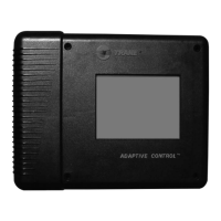
Installation Instructions
Tracer® MP581/AH541
or Tracer Summit™
BMTX BCU Operator Display
Door Upgrade
This installation instruction provides the procedures to:
Set Up the Operator Display
Removing/Installing the Enclosure Door
Adjusting the Operator Display
3270 3395

Questions and Answers

Overview

The Trane Tracer® MP581/AH541 or Tracer Summit™ BMTX BCU Operator Display Door Upgrade is a comprehensive solution designed to enhance the functionality and user experience of Trane's control systems. This upgrade primarily focuses on the operator display and its enclosure, providing detailed instructions for setup, installation, and maintenance.

Function Description

The core function of this upgrade is to facilitate the installation and proper functioning of the operator display within its enclosure. The operator display serves as the primary human-machine interface for Trane's Tracer MP581/AH541 programmable controllers and Tracer Summit BMTX BCU systems. It allows users to monitor system status, adjust settings, and interact with the building management system. The upgrade ensures that the display is correctly integrated into the system, providing a reliable and accessible interface for system operation and management.

The upgrade process involves several key steps: setting up the operator display, removing and installing the enclosure door, and adjusting the operator display's brightness and contrast. These steps are crucial for ensuring the display is fully operational and optimized for user interaction. The manual emphasizes the importance of proper installation and calibration to achieve optimal performance and longevity of the device.

Usage Features

The operator display offers several user-friendly features designed to enhance interaction with the control system.

  • Intuitive Setup: The initial setup of the operator display involves calibrating the touch screen. This is achieved by pressing a "Setup" button on the Home screen, navigating to the calibration option, and then touching specific targets on the screen with a blunt object until a beeping sound stops. This two-point calibration ensures accurate touch response, making the interface reliable and easy to use. The manual explicitly warns against using sharp objects during calibration to prevent damage to the screen.
  • Adjustable Display Settings: Users can adjust the brightness and contrast of the operator display to suit different lighting conditions and personal preferences. For Tracer MP581 or Tracer AH541 models, these adjustments are made through the "Adjust Brightness and Contrast" option found after pressing "Setup" and "Page Down." Brightness and contrast are increased or decreased by pressing buttons along the top and bottom rows, respectively. For BMTX models, the "Backlight and Contrast" button provides similar functionality. This flexibility ensures optimal visibility and reduces eye strain during prolonged use.
  • Enclosure Door Management: The design allows for easy removal and installation of the enclosure door. The door can be opened to a 90-degree angle and then lifted to disengage its hinge pegs from the enclosure holes. Reinstallation is a reverse process, ensuring the door aligns correctly and rests securely. Magnetic latches are incorporated to hold the door firmly when closed, providing protection for the internal components. This feature is essential for maintenance and access to the internal wiring and components.
  • Cable Management: The operator display cable connects the display to the main board. The installation instructions highlight the importance of proper cable routing, noting that the cable passes beneath the termination board in factory-installed operator display enclosures. Securing the cable with a wire or plastic tie is recommended to prevent accidental disconnections or damage, contributing to the overall reliability of the system.

Maintenance Features

The manual provides clear guidelines for maintaining the operator display and its enclosure, focusing on safety and longevity.

  • Cleaning the Display: For cleaning the operator display, the manual recommends using a soft cloth and glass cleaner. It specifically warns against spraying water or other cleaners directly onto the screen, as this could cause damage. This simple maintenance tip helps preserve the screen's clarity and responsiveness.
  • Safety Warnings and Precautions: Throughout the manual, significant emphasis is placed on safety. "WARNING" advisories indicate potentially hazardous situations that could result in death or serious injury if not avoided. "CAUTION" advisories point to situations that could lead to minor or moderate injury. "NOTICE" advisories highlight situations that could result in equipment or property damage.
  • Qualified Personnel Requirement: A critical safety warning states that only qualified personnel should install and service the equipment. This is due to the hazardous nature of heating, ventilating, and air-conditioning equipment, which requires specific knowledge and training. Improper installation or servicing by unqualified individuals could lead to death or serious injury.
  • Personal Protective Equipment (PPE): The manual mandates the use of appropriate Personal Protective Equipment (PPE) when installing or servicing the unit. This includes protection against electrical, mechanical, and chemical hazards. Technicians are instructed to refer to SDS sheets and OSHA guidelines for proper PPE, especially when working with hazardous chemicals or where there is a risk of arc or flash. Compliance with NFPA70E for arc/flash protection is specifically mentioned.
  • Proper Field Wiring and Grounding: Another crucial safety warning emphasizes the necessity of proper field wiring and grounding, performed by qualified personnel. Improper wiring poses fire and electrocution hazards. Users are directed to follow NEC and local/state electrical codes for all wiring installations.
  • Environmental Responsibility: The manual includes sections on important environmental concerns and responsible refrigerant practices. While not directly a maintenance feature of the display itself, it underscores Trane's commitment to environmental stewardship, urging technicians to handle refrigerants responsibly and adhere to federal and local regulations. This reflects a broader maintenance philosophy that extends beyond the immediate device to the entire HVAC system and its environmental impact.
  • Pre-installation Checks: Before installing the enclosure door, users are instructed to unpack it and check for missing or damaged parts. They must also ensure that the touch screen and magnetic latches are installed and check for cracks in the plastic. These pre-installation checks are vital for preventing issues down the line and ensuring a successful installation.

In summary, the Trane Tracer® MP581/AH541 or Tracer Summit™ BMTX BCU Operator Display Door Upgrade provides a robust and user-centric solution for integrating and maintaining the operator display within Trane's control systems. Its design prioritizes ease of use, safety, and long-term reliability, ensuring that the display remains a functional and effective interface for managing complex building environments.

Trane Tracer MP581/AH541 Specifications

General IconGeneral
ModelTracer MP581/AH541
Controller TypeMicroprocessor-based
DisplayLCD
Input Voltage24VAC
TypeController
Communication ProtocolBACnet
Operating Temperature0 to 50°C
Relative Humiditynon-condensing
MemoryFlash memory
InputsUniversal (Analog/Digital)
OutputsUniversal (Analog/Digital)

Related product manuals