32 18-CD33D1-4
Installer’s Guide
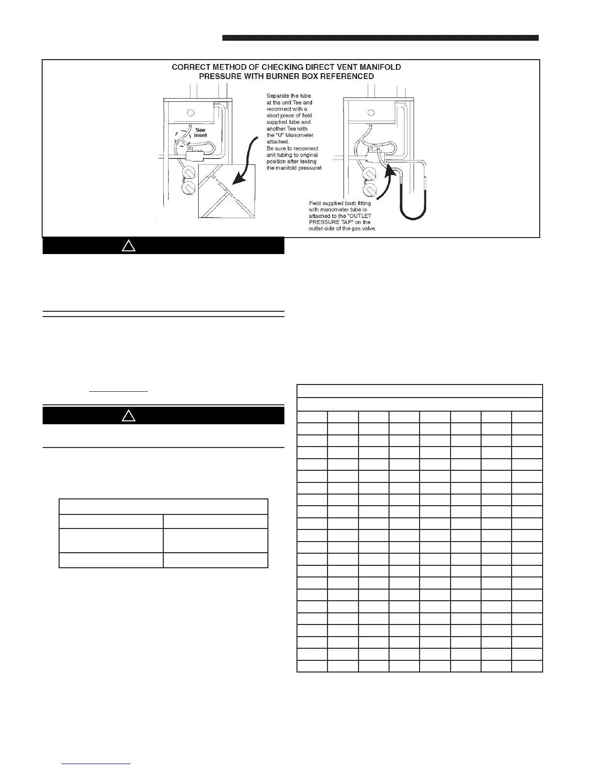
GAS FLOW IN CUBIC FEET PER HOUR
2 CUBIC FOOT DIAL
SEC. FLOW SEC. FLOW SEC. FLOW SEC. FLOW
8 900 29 248 50 144 82 88
9 800 30 240 51 141 84 86
10 720 31 232 52 138 86 84
11 655 32 225 53 136 88 82
12 600 33 218 54 133 90 80
13 555 34 212 55 131 92 78
14 514 35 206 56 129 94 76
15 480 36 200 57 126 96 75
16 450 37 195 58 124 98 73
17 424 38 189 59 122 100 72
18 400 39 185 60 120 104 69
19 379 40 180 62 116 108 67
20 360 41 176 64 112 112 64
21 343 42 172 66 109 116 62
22 327 43 167 68 106 120 60
23 313 44 164 70 103 124 58
24 300 45 160 72 100 128 56
25 288 46 157 74 97 132 54
26 277 47 153 76 95 136 53
27 267 48 150 78 92 140 51
28 257 49 147 80 90 144 50
TABLE 13
Q
Input rate changes can be made by adjusting the mani-
fold pressure (min 3.0 - max 3.7 in. W.C. - Natural Gas) or
changing orifices (orifice change may not always be re-
quired). If the desired input rate can not be achieved with
a change in manifold pressure, then the orifices must be
changed. LP installations will require an orifice change.
Installation of this furnace at altitudes above 2,000 ft.
(610m) shall be in accordance with local codes, or in the
absence of local codes, the National Fuel Gas Code,
Replace and/ or tighten all plugs removed or loosened
when adjusting gas pressure. Leak check the fittings
before placing the furnace into regular service.
Failure to follow this warning could result in fire, explo-
sion, or property damage.
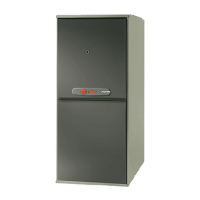
NOTE:
The manifold pressure must be referenced to the burn-
er box. The burner box pressure tap equalizes the gas
valve pressure regulator. Manifold pressure is checked
by installing a tee (field supplied) in the tubing, be-
tween the tee coming from the burner box tube and the
gas valve, in addition to the regular gas valve pressure
tap on the outlet side of the gas valve. See Figure 51.
Replace manifold pressure tap threaded plug and leak
check after checking/ adjusting manifold gas pressure.
Table 11 lists the main burner orifices used with the fur-
nace. If a change of orifices is required to correct the fur-
nace input rating refer to Table 14.
TABLE 12
FINAL MANIFOLD PRESSURE SETTINGS
FUEL PRESSURE
NATURAL GAS 3.5" W.C.
LP GAS 11.0" W.C.
HIGH ALTITUDE DERATE
Input ratings (BTUH) of these furnaces are based on sea
level operation and should not be changed at elevations
up to 2,000 ft.
If the installation is 2,000 ft. or above, the furnace input
rate (BTUH) shall be reduced 4% for each 1,000 ft. above
sea level. The furnace input rate shall be checked by
clocking the gas flow rate (CFH) and multiplying by the
heating value obtained from the local utility supplier for
the gas being delivered at the installed altitude.