EasyManua.ls Logo

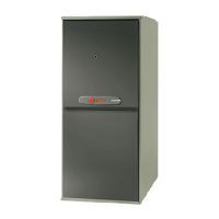
Trane TUH1C100A9481A

Trane TUH1C100A9481A
40 pages
To Next Page IconTo Next Page
Loading...
Upflow/ Horizontal, Downflow/ Horizontal,
Gas-Fired, Direct Vent Condensing
Furnaces
ALL phases of this installation must comply with NATIONAL, STATE AND LOCAL CODES
IMPORTANT — This Document is customer property and is to remain with this unit.
Please return to service information pack upon completion of work.
Installer’s Guide
*__First letter may be “A” or “T”
UPFLOW
*UH1
UPFLOW/HORIZONTAL
A341624P13
*UH1
*UH1B040A9241A
*UH1B060A9361A
*UH1B080A9421B
*UH1C080A9601A
*UH1C100A9481A
*UH1D100A9601A
*UH1D120A9601A
*DH1B040A9241A
*DH1B065A9421A
*DH1C085A9481A
*DH1D110A9601A
*DH1
DOWNFLOW
DOWNFLOW/HORIZONTAL
*DH1
18-CD29D1-11

Table of Contents

Question and Answer IconNeed help?

Do you have a question about the Trane TUH1C100A9481A and is the answer not in the manual?

Trane TUH1C100A9481A Specifications

General IconGeneral
ModelTUH1C100A9481A
TypeUpflow
Heating Capacity100, 000 BTU
Efficiency Rating80% AFUE
Fuel TypeNatural Gas
Ignition TypeHot Surface Ignition
Heat ExchangerAluminized Steel
Weight140 lbs
Installation TypeUpflow
Vent TypeCategory I

Summary

SAFETY SECTION

Location and Clearances

Upflow Installation

Details for furnace installation in an upflow configuration, including coil placement.

AIR FOR COMBUSTION AND VENTILATION

GENERAL VENTING

FURNACE VENT INLET PIPE INSTALLATION

MAXIMUM VENT LENGHT TABLE

DOWNFLOWHORIZONTAL VENTING TABLE

Direct Vent Terminal Clearances

Non-Direct Vent Terminal Clearances

Clearances required for non-direct vent terminations.

IMPORTANT: The Commonwealth of Massachusetts requires compliance...

INSTALLATION OF CARBON MONOXIDE DETECTORS.

Requirements for installing carbon monoxide detectors with side wall venting.

APPROVED CARBON MONOXIDE DETECTORS.

Specifications for approved carbon monoxide detectors.

HORIZONTAL INSTALLATION UpflowHorizontal

CONDENSATE DRAIN INSTRUCTIONS VERTICAL APPLICATIONS

Instructions for condensate drain connections in vertical installations.

HORIZONTAL APPLICATIONS Upflow and Downflow furnaces

CONDENSATE DRAIN INSTRUCTIONS

Details on condensate drain connections for horizontal applications.

FIELD WIRING DIAGRAM FOR 1 STAGE FURNACE

ELECTRICAL CONNECTIONS

Instructions for making electrical connections to the furnace.

TWINNING CONNECTION DIAGRAM FOR TWINNING 1 STAGE FURNACES WITH SINGLE WIRE TWINNING FEATURE

TWINNING CONNECTION DIAGRAM FOR TWINNING 1 STAGE FURNACES WITH SINGLE WIRE TWINNING FEATURE

Diagrams for connecting two furnaces for simultaneous operation.

GAS PIPING

GAS VALVE ADJUSTMENT

HIGH ALTITUDE DERATE

LIGHTING INSTRUCTIONS

WARNING CARBON MONOXIDE POISONING HAZARD

Warning about ventilation system operation and carbon monoxide.

START UP AND ADJUSTMENT

Procedure for starting up and adjusting the furnace.

SEQUENCE OF OPERATION

AIRFLOW ADJUSTMENT

Instructions for adjusting airflow by changing blower motor speed.

ABNORMAL CONDITIONS

1. EXCESSIVE COMBUSTION PRESSURE (WIND IN EXCESS OF 40 M.P.H.) VENT OR FLUE BLOCKAGE

Troubleshooting excessive combustion pressure due to vent blockage.

2. LOSS OF FLAME

Troubleshooting loss of flame during operation.

INTEGRATED FURNACE CONTROL ERROR FLASH CODES

Related product manuals