22 18-CD29D1-11
Installer’s Guide
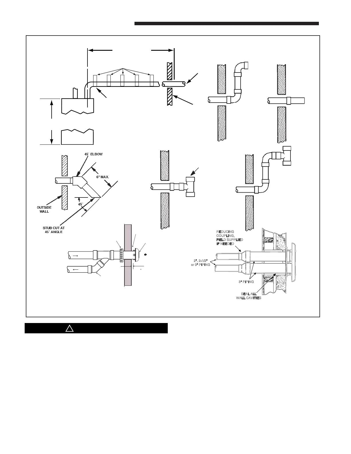
NOTE: VENT AND INLET MUST BE SUPPORT-
ED AT A MAXIMUM OF 3' INTERVALS
40" UPFLOW OR
DOWNFLOW MODELS
SEE VENTING TABLE
OUTSIDE
WALL
NOTE: ANY FITTINGS PASSING
THROUGH AN UNHEATED SPACE
MUST BE INSULATED.
FIRST SUPPORT SHOULD BE AS
CLOSE TO FURNACE CONNECTION
AS POSSIBLE.
UPWARD PITCH -- 1/4" PER FOOT
STRAPS OR OTHER SUITABLE SUPPORTS
AT MAXIMUM OF 3'-0" INTERVALS
COMBUSTION
AIR INLET
USE ONLY
APPROVED
TERMINATION
TEE
RAIN CAP
COMBUSTION AIR
STRAP
(FIELD SUPPLIED)
COMBUSTION
AIR
VENT
ELBOW
(FIELD
SUPPLIED)
VENT
1" + 1/2"
BAYAIR30AVENTA
3" PIPING
2", 2-1/2"
or 3" PIPING
REDUCING
COUPLING,
FIELD SUPPLIED
IF NEEDED
SEAL ALL
WALL CAVITIES
BAYVENT200B
c
The vent for this appliance shall not terminate
(1) Over public walkways; or
(2) Near soffit vents or crawl space vents or other
areas where condensate or vapor could create a
nuisance or hazard or cause property damage; or
(3) Where condensate vapor could cause damage or
could be detrimental to the operation of regula-
tors, relief valves. or other equipment.
For Canadian applications, horizontal vent termination kits must meet ULC-S636.