18-CD19D5-25 17
Installer’s Guide
PIPE JOINTS: All joints must be fastened and sealed to
prevent escape of combustion products into the build-
ing.
NOTE:
It is recommended that the first joints from the furnace
be connected and sealed with high temperature RTV.
This will enable the pipes to be removed later without
cutting.
Be sure to properly support these joints.
BONDING OF PVC
Commercially available solvent cement must be used
to join the pipe and fittings. Follow instructions on the
container carefully.
5. Wipe all excess cement from the joint with a rag.
Allow 15 minutes before handling. Cure time varies
according to fit, temperature and humidity.
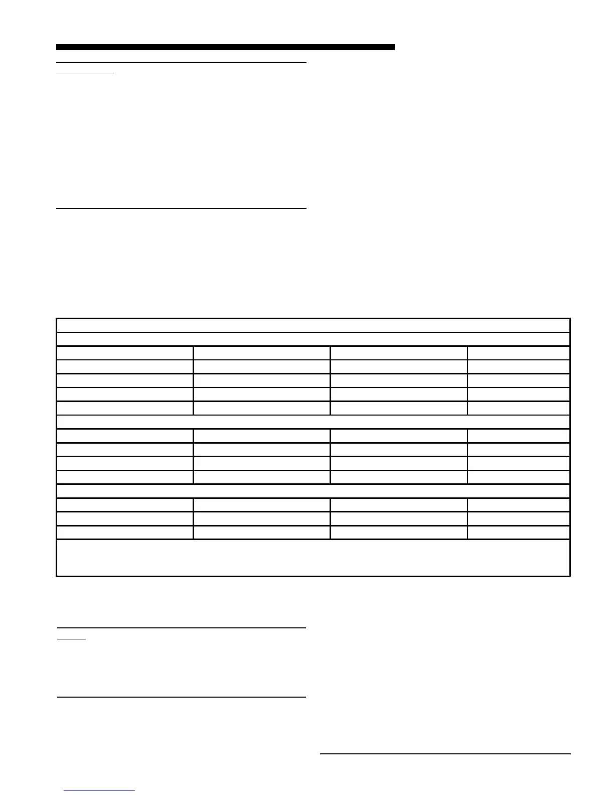
TABLE 9
PLASTIC PIPE DESIGNATIONS
PVC
ASTM STANDARD PIPE TYPE ALLOWABLE TEMPERATURE MARKING
F891 CELLULAR CORE *158 ASTM F891
D2665 DWV PIPE **158 ASTM D2665
D1785 SCH 40, 80, 120 **158 ASTM D1785
D2241 SDR SERIES **158 ASTM D2241
CPVC
ASTM STANDARD PIPE TYPE ALLOWABLE TEMPERATURE MARKING
D2846 CPVC 41 **212 ASTM D2846
F441 SCH 40, 80 **212 ASTM F441
F442 SDR SERIES **212 ASTM F442
ABS
ASTM STANDARD PIPE TYPE ALLOWABLE TEMPERATURE MARKING
D2661 SCH 40 DWV ***180 ASTM D2661
F628 SCH 40 DWV CELLULAR CORE ***180 ASTM F628
* - Allowable temperatures based on classifications covered in ASTM D4396 [Deflection Temps Under Load (264 PSI)]
** - Allowable temperatures based on classifications covered in ASTM D1784 [Deflection Temps Under Load (264 PSI)]
*** - Allowable temperatures based on classifications covered in ASTM D3965 [Deflection Temps Under Load (264 PSI)]
IMPORTANT:
These furnaces may be installed as Direct Vent (sealed
combustion) or as Nondirect vent (single pipe). The fur-
naces are shipped DIRECT VENT with sealed combustion.
For DIRECT VENT APPLICATION: The furnaces must be
vented to the exterior of the house and combustion air
MUST come through the inlet air pipe FROM OUTSIDE
AIR.
For NONDIRECT VENT APPLICATION: The furnace shall
be vented to the exterior of the house, but combustion air
may enter from the surrounding area as long as combus-
tion air requirements are met. (See AIR FOR COMBUS-
TION AND VENTILATION)
VENT FITTING MATERIAL – PLASTIC
Gas and liquid tight single wall vent fittings, designed
for resistance to corrosive flue condensate, MUST be
used throughout.
Listed in Table 10 & 11 are 2", 2½", 3", and 4" size fittings
that meet these requirements. The materials listed are
various grades of PVC and ABS plastic.
Procedure for Cementing Joints:
1. Cut pipe square, remove ragged edges and burrs.
Chamfer end of pipe, then clean fitting socket and
pipe joint area of all dirt, grease, moisture or chips.
2. After checking pipe and socket for proper fit, wipe
socket and pipe with cleaner-primer. Apply a liberal
coat of primer to inside surface of socket and out-
side of pipe.
DO NOT ALLOW PRIMER TO DRY BEFORE AP-
PLYING CEMENT.
3. Apply a thin coat of cement evenly in the socket.
Quickly apply a heavy coat of cement to the pipe
end and insert pipe into fitting with a slight twisting
movement until it bottoms out.
4. Hold the pipe in the fitting for 30 seconds to pre-
vent tapered socket from pushing the pipe out of
the fitting.
Important:
Products installed in Canada must use vent systems
that are certified to the Standard for Type BH Gas
Venting Systems (ULC S636) for Class II-A venting
systems (up to 65 degrees C). Components of the vent
system must not be interchanged with other vent sys-
tems or unlisted pipe or fittings. Plastic components,
specified primers, and glues must be from a single
system manufacturer and not intermixed with other
system manufacturer’s vent system parts. In addition,
the first three feet of the vent pipe must be visible for
inspection.
 Loading...