Principles of Operation of the
Module UCM-CLD
RLC-SVU02F-E44
General Information
This UCM-CLD chiller control is
composed of eight electronic
modules, which each have their
own 115V or 24V power supply and
communicate with each other via a
serial link. The names of the
modules are linked to their
functions.
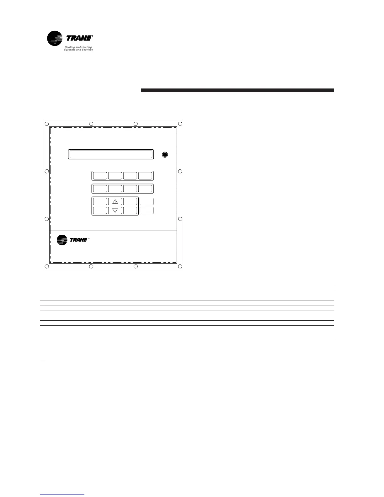
Figure 1 : Operator’s interface
Module Functions
MCSP (Motor Compressor Start and Protection)
CPM (Chiller Protection and Management) Safety, protection, and control of the chiller
EXV (Electronic Expansion Valves) Control of both electronic expansion valves
CSR (Communication and Setpoint Reset) ,
Local CLD (Local Clear Language Display) Operator interface located in the front panel of the unit
Remote CLD (Remote Clear Language Display)
TCI IV, COM 3 (Tracer Communication Interface 4, COM 3)
Safety, protection, and control of the helical-rotary compressor and
its components
Control of the serial communication, unit external setpoints and
ice-making mode (optional module)
Operator interface located up to 1500m from the unit, able to
communicate with up to four units of the same type (optional module)
TCI IV, IPCB (Tracer Communication Interface 4, Inter Processor
Communication Buffer)
Protection of the internal communication bus in the unit from external
interferences (optional factory-mounted module, compulsory when
using a Remote CLD)
Interface between the control of the unit and a Building Management
System using Trane COMM 3 serial link