Do you have a question about the Trane UCM-CLD and is the answer not in the manual?
Introduction to the manual's purpose and scope for the UCM-CLD controller.
Explanation of warning symbols and safety recommendations for proper operation.
Key safety precautions to observe during maintenance and service visits.
Steps for inspecting the unit upon arrival and reporting any damage.
Details on warranty terms and conditions, including voiding factors.
Recommendation to sign a maintenance contract for regular specialized service.
Information on available training services for better equipment use and maintenance.
Description of the UCM-CLD chiller control's composition of eight electronic modules.
Details the functions of individual modules like MCSP, CPM, EXV, CSR, and communication interfaces.
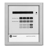
Explains the digital display and the 16-key touchpad keyboard for navigation and control.
Details the 2-line, 40-character LCD display, its backlight, and what it shows.
Describes the 16-key touchpad, divided into menu navigation and control keys.
Detailed explanation of the functions of the '+', '-', 'Previous', 'Next', 'Enter', 'Cancel', 'Auto', and 'Stop' keys.
Lists parameters and their ranges for Chiller, Custom, Refrigerant, Compressor, and Operator Settings menus.
Details settings adjustable by the customer and service engineer across three access levels.
Lists available service tests such as expansion valve and compressor tests.
Lists functions for viewing current diagnostics, history, and resetting.
Covers features like entering evaporator water temperature and current limit setpoints.
Explains how the UCM monitors entering and leaving water temperatures to detect flow loss.
Details how current limit setpoints are entered and managed for compressor protection.
Procedure for testing the EXV operation, including overdrive sequences.
Describes UCM's monitoring of compressor current for overcurrent or locked-rotor protection.
Explains how the UCM controls to a setpoint, including actions upon start-up temperature changes.
Details the CWR option that resets the chilled-water setpoint based on water temp or outdoor air.
Explains the cutout for freeze protection, its setpoints, and diagnostic triggers.
Describes protection against low saturated-evaporator refrigerant temperature and related diagnostics.
Feature to balance compressor operating hours and starts for even wear.
Details how the UCM monitors phase imbalance and protects compressors.
Explains the protection against reverse rotation and the importance of correct power phasing.
Describes the logic for detecting oil line restrictions based on oil and condenser temperatures.
Details the DIP switch settings for compressor overload and IPC address configuration.
Configuration of 2-10V or 4-20mA inputs for external chilled water setpoints and current limits.
Details the LCWT control option for model RTWB, its DIP switch setting, and function.
Shows pressure switch settings for high and low pressure for different approval standards.
Details the RTWB's hot-water mode operation, scope of supply, and sequence of operation.
Explains the unit's operation in cooling mode and heating mode for hot-water applications.
Describes chiller shutdown and alarm actions when the CDS leaving-water temperature sensor fails.
Explains how the A70 module interacts with the UCM for setpoints, enable/disable, and pump control.
Describes the different unit control modes: No, Partial, and Full, based on user settings.
Details the analog input for external cooling setpoints, its scaling, and configuration.
Details the analog input for external heating setpoints, its scaling, and configuration.
Explains the digital input for external unit ON/OFF control.
Details the digital input for selecting the external heat or cool mode.
Message displayed when no active diagnostics are present.
Describes common diagnostic messages like machine shutdown or circuit shutdown.
Explains the flashing of the red LED for manual reset shutdowns versus other states.
Lists the priority order of active diagnostics from highest to lowest.
Lists default descriptions for various fault codes, their types (MMR, CMR, IFW, MAR), and causes.
Lists fault codes and their types and descriptions for system malfunctions.
Provides further fault codes, types, and detailed descriptions for various system issues.
Lists additional fault codes related to oil system, fan drive, and sensor issues with their types.
Lists fault codes specific to communication failures between different modules.
Details the control terminal's LCD display and six buttons (Alarm, Program, Escape, Arrows, Validate).
Explains the basic control logic for turning the system on and its reaction to sensor failures.
Describes system reactions to failures in Entering Water Temperature and Ambient Air Temperature sensors.
Details the electric heater and pump activation for freeze protection based on ambient temperature.
Explains pump start/stop, automatic change-over on pump failure, and freeze protection by pump activation.
Lists all inputs (EWT, OAT, Pump, Flow, System) and outputs (Pumps, Heaters, FS, Alarm) with their terminals.
Details the permanent display of application name, date, time, and unit status.
Describes the information shown on the permanent display, including application name, date, and unit status.
Explains how to access sub-menus like Data Display, Settings, Clock, and Configuration using the Prg key.
Details the data display menu, showing Analog Inputs, Digital Inputs, Digital Outputs, and Counters.
Explains how to access and modify fields in the Settings Menu, including User Password and User Settings.
Details the Clock Menu, allowing access to Clock Settings via User Password.
Lists alarm messages for the hydraulic module, including screen, events, reset type, unit status, and description.
Details the permanent display of Free Cooling application name, date, time, and unit status.
Describes the information shown on the permanent display, including FC application, date, and unit status.
Explains how to access sub-menus like Data Display, Settings, Clock, and Configuration.
Details the data display menu, showing Analog Inputs and Setpoint Source information.
Lists analog inputs like Ent Wat Temp, Lvg Wat Temp, Ambient Temp, and Active SP.
Explains the different sources for setpoints (Front Panel, External, Air Reset, Return Water Reset).
Lists digital inputs such as System status, UCM Pump status, Flow Switch, and Free Cooling enable.
Details digital outputs for Fans, FC status, UCM enabled, System Pump, Flow Switch, and PRG Relay.
Describes the Input/Output for the 3-way valve, showing position and analog voltage.
Details the Input/Output for chilled water setpoints, including external and adjusted values.
Explains access to settings like User Password, User Settings (Lvg Water SP, Delta Temp SP, Pump OFF Delay, PRG Relay).
Details CWR parameters: Reset Type, Ratio, Start Temperature, and Maximum CWR.
Details the Clock Menu, allowing access to Clock Settings via User Password.
Lists alarm messages for Free Cooling, including sensor faults, flow switch issues, and 3WV position errors.
Describes the permanent display of HR application, date, time, hot water temp, and unit status.
Explains how to access sub-menus like Data Display, Settings, Clock, and Configuration.
Details the data display menu, showing Analog Inputs like Hot Water Temp and pressures.
Lists analog inputs for Hot Water Temp, Circuit 1 pressure, Circuit 2 pressure, and Active hot water setpoint.
Lists digital inputs for Circuit status, HR status, and Night Noise Set Back.
Details digital outputs for Fans, Programmable Relay, and enable outputs for circuits.
Lists analog outputs for 3-Way valve, C1 Speed Inverter, and C2 Speed Inverter.
Explains access to settings like User Password, User Settings (Hot Water SP, PRG Relay).
Details the Clock Menu, allowing access to Clock Settings via User Password.
Lists alarm messages for Heat Recovery, including sensor faults and pressure errors.
Describes the permanent display of RTWB HP application, date, time, and CDS LWT.
Explains how to access sub-menus like Data Display, Settings, Clock, and Configuration.
Details the data display menu, showing Binary and Analog Inputs.
Lists binary inputs (CDSLWT, EXTSTST, EXTMODE, CDSPPRQT) and their status.
Details binary outputs for Active Mode, Unit Status, CDS Pump Status, and Sensor Alarm.
Shows active setpoints for Mode, Heating Setpoint, and Cooling Setpoint, influenced by external control.
Explains access to settings like User Password, User Settings 1 (Heat/Cool Setpoints, External Control).
Details front panel heat/cool setpoints, heat/cool switch, and external control settings.
Details external setpoint input types (0-1V, 4-20mA) for heat and cool, displayed for 'Full' external control.
Details the Clock Menu, allowing access to Clock Settings via User Password.
Lists alarm messages for RTWB Heat Pump, including CDS LWT sensor fault.
| Brand | Trane |
|---|---|
| Model | UCM-CLD |
| Category | Chiller Control System |
| Language | English |