Do you have a question about the Trane UD060R9V3K Series and is the answer not in the manual?
Essential safety guidelines for installation, servicing, and operation of the furnace.
Critical warnings regarding carbon monoxide, fire, explosion, and other significant risks.
Manufacturer's responsibilities, code compliance, and equipment handling.
Guidelines for selecting furnace placement and required clearances to combustible materials.
Specific installation methods for upflow, downflow, and horizontal furnace configurations.
Requirements for providing adequate air for furnace operation and ventilation.
Procedures for connecting ducts and installing return air filters.
Guidelines for safe and compliant venting of furnace flue gases.
Standards and practices for connecting the gas supply to the furnace.
Guidelines for making safe and compliant electrical connections and wiring.
Procedures for checking and adjusting limit switches and blower controls.
Procedure for verifying correct gas input rate and combustion performance.
Steps for initial furnace operation, including inspections, lighting, and sequence checks.
Identification of malfunctions, first aid, and troubleshooting with error codes.
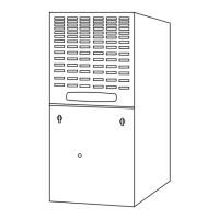
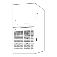
This document serves as an installer's guide for variable speed, two-stage, gas-fired furnaces, specifically designed for upflow/horizontal and downflow/horizontal configurations, featuring a "Fan Assisted Combustion System." It provides comprehensive instructions for installation, start-up, adjustment, and maintenance, ensuring safe and efficient operation.
The furnaces described are fan-assisted combustion system, Category I gas-fired units. They are designed to provide heating for residential and light commercial applications. The two-stage operation allows for modulated heating, offering improved comfort and energy efficiency by adjusting the heat output based on demand. The variable speed blower motor further enhances comfort by providing consistent airflow and quiet operation. These furnaces are capable of operating with either natural gas or LP gas, with specific adjustments required for each fuel type and for installations at high altitudes. The integrated furnace control (IFC) manages the sequence of operation, including ignition, flame sensing, and blower control, ensuring safe and reliable performance. Safety features such as limit switches and pressure switches are incorporated to prevent overheating and ensure proper venting.
The guide details various installation configurations, including upflow, downflow, and horizontal orientations. For upflow installations, the furnace can be installed with a cased coil placed on top, and filter racks are factory supplied for bottom or side return air inlets. Horizontal installations allow for placement in attics or crawl spaces, with specific requirements for support and clearances. Downflow furnaces require a subbase for combustible flooring, unless a cased coil is installed vertically. The return air filter system is designed for flexibility, allowing filters to be located within the blower compartment for upflow models or externally for horizontal and downflow applications. The blower door is hinged for easy filter replacement and maintenance access.
The two-stage heating operation is controlled by a thermostat. A single-stage thermostat will initiate a 10-minute delay before the second stage engages, while a two-stage thermostat directly controls both stages. The variable speed blower motor provides quiet and efficient air delivery, with adjustable fan-off delays for both heating and cooling cycles. An "Enhanced Mode" is available for cooling, which ramps up and down the blower speed to improve comfort, quietness, and energy savings. This mode is particularly beneficial for dehumidification. The guide also covers the necessary adjustments for manifold pressure and orifices, which are critical for optimizing performance based on fuel type and altitude.
The guide emphasizes several maintenance-related aspects to ensure the longevity and safe operation of the furnace. Regular inspection of the venting system is crucial to check for proper size, pitch, blockages, restrictions, leakage, or corrosion. Filters are a key maintenance item, and the guide provides detailed instructions on their installation, removal, and replacement. It highlights the importance of using high-velocity type air filters and specifies that filters should not be installed directly above the furnace in horizontal applications to prevent property damage or injury. The blower door is designed for easy removal and tilting, facilitating access for filter changes and internal inspections.
Safety checks are paramount, including testing for gas leaks with a soap solution (never an open flame) and verifying the proper operation of the limit switch. The limit switch check involves intentionally restricting airflow to ensure the burners shut off when the furnace reaches its maximum outlet temperature. The guide also provides instructions for resetting the integrated control module after a lockout condition. For installations in residential garages, the furnace must be located to avoid physical damage from vehicles. The document also includes warnings about carbon monoxide poisoning and the importance of proper combustion and ventilation air supply. It advises against using the furnace as a "Construction Heater" during the finishing phases of construction to prevent corrosive conditions that could damage the heat exchanger. The guide also recommends that homeowners be instructed on how to shut off the gas supply and electrical power in case of a malfunction and to contact a qualified service agency for repairs.
| Model | UD060R9V3K |
|---|---|
| Category | Furnace |
| Manufacturer | Trane |
| Fuel Type | Natural Gas |
| Input BTU/h | 60, 000 |
| Blower Motor | Variable Speed |
| Blower Type | Multi-Speed |
| Heat Exchanger Material | Stainless Steel |
| Series | UD |
| Ignition Type | Hot Surface |
| Warranty | 10 Years |