EasyManua.ls Logo

Trane UD2B060ACV32A Series - User Manual

Trane UD2B060ACV32A Series
36 pages
Print Icon
To Next Page IconTo Next Page
Loading...
Variable Speed, 2-Stage Communicating or 24V
Upflow / Horizontal and Downflow / Horizontal,
Gas-Fired Furnaces, “Fan Assisted
Combustion System”
A341789P11
Installer’s Guide
Downflow / Horizontal 2
Upflow / Horizontal 1
For VENT SIZING INFORMATION see:
USA
National Fuel Gas Code ........... ANSI Z223.1/NFPA 54 (latest version)
CANADA
Natural Gas Installation Code ........CAN/CGA-B149.1 (latest version)
Propane Installation Code ............... CAN/CGA-B149.2 (latest version)
USA/CANADA ALTERNATE
Category I Venting Guide ...........Pub. No. 18-CH23D1 (latest version)
1 Horizontal Conversion for these furnaces may be left or right side rotation.
2 Horizontal Conversion for these furnaces may be left or right side rotation (Important: See venting applications, page 8).
ALL phases of this installation must comply with NATIONAL, STATE AND LOCAL CODES
IMPORTANT — This Document is customer property and is to remain with this unit.
Please return to service information pack upon completion of work.
* First letter may be “A” or “T”
*UD2B060ACV32A
*UD2B080ACV32A
*UD2C080ACV42A
*UD2B100ACV32A
*UD2C100ACV52A
*UD2D120ACV52A
*UD2D140ACV52A
*DD2B060ACV32A
*DD2B080ACV32A
*DD2C100ACV52A
*DD2D120ACV52A
*DD2-ACV
*UD2-ACV
Left
Right
18- CD32D1- 3
18- CD32D1- 3
Question and Answer IconNeed help?

Do you have a question about the Trane UD2B060ACV32A Series and is the answer not in the manual?

Overview

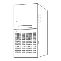
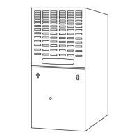
This document is an Installer's Guide for Variable Speed, 2-Stage Communicating or 24V Upflow/Horizontal and Downflow/Horizontal, Gas-Fired Furnaces, featuring a "Fan Assisted Combustion System." The guide provides comprehensive instructions for the installation, setup, adjustment, and maintenance of these furnaces.

Function Description:

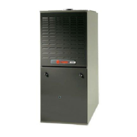
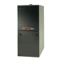
The furnaces described are gas-fired units designed for residential heating applications. They offer variable speed operation and can function in either 2-stage communicating mode or 24V mode. The units are designed for both upflow/horizontal and downflow/horizontal installations. The "Fan Assisted Combustion System" indicates that a fan aids in the combustion process, ensuring efficient and safe operation. These furnaces can support various heating and cooling applications, including single or multi-stage heat pumps and AC units, and heating-only configurations. When combined with a communicating Comfort Control, they can also support a single-stage 24V cooling outdoor unit.

Important Technical Specifications:

The guide lists several models with specific dimensions (A, B, C, D) for different cabinet widths:

  • **17-1/2" models (e.g., UD2B060ACV32A, DD2B060ACV32A): A: 17-1/2", B: 9-5/8", C: 16-1/4", D: 16"
  • **21" models (e.g., UD2C080ACV42A, DD2C100ACV52A): A: 21", B: 13-1/16", C: 19-3/4", D: 19-1/2"
  • **24-1/2" models (e.g., UD2D120ACV52A, DD2D120ACV52A): A: 24-1/2", B: 15-5/16", C: 23-1/4", D: 23"

Minimum Clearances to Combustible Materials:

  • Upflow Closet: Left Side: 0 in., Front: 3 in., Right Side: 0 in., Back: 0 in., Flue: 6 in., Top: 1 in. (may be 1" when Type B-1 vent is used).
  • Horizontal Closet: Top: 2 in., Back: 3 in., Flue: 6 in., Sides: 1 in., Front: 18 in. (may be installed on combustible floor when Type B-1 vent is used).
  • Horizontal Alcove: Top: 1 in., Back: 0 in., Flue: 6 in., Sides: 0 in., Front: 18 in.

Electrical Specifications:

  • The maximum total cable length for the entire Comfort Control communicating system is 500 ft. of 18 AWG wire.
  • The maximum distance of any single cable from a transformer is 250 ft. of 18 AWG wire.
  • The hot leg of the 120V power supply must be connected to the black field lead. The furnace control is polarity sensitive.
  • A 5 Amp control fuse is present on the IFC board.

Gas Piping Specifications:

  • Natural Gas: Maximum pressure to gas valve: 13.8" W.C., Minimum pressure: 5.0" W.C.
  • LP Gas: Maximum pressure to gas valve: 13.8" W.C., Minimum pressure: 11.0" W.C.
  • Final Manifold Pressure Settings:
    • Natural Gas: 1st Stage Max: 1.7" W.C., 2nd Stage Max: 3.5" W.C.
    • LP Gas: 1st Stage Max: 6.0" W.C., 2nd Stage Max: 10.5" W.C.
  • Orifice Sizes: For 60,000 to 140,000 BTUH input ratings, natural gas uses #45 orifices, and LP gas uses #56 orifices. Replacement orifices are available for various drill sizes.

Air for Combustion and Ventilation:

  • Minimum free area in square feet for unconfined space installations (with 8 ft. ceiling): 375 sq. ft. for 60,000 BTUH to 875 sq. ft. for 140,000 BTUH.
  • Minimum free area in square inches for each opening (furnace only) for air from outside: 15-35 sq. in. for vertical duct, 30-70 sq. in. for horizontal duct, depending on BTUH input.

Usage Features:

  • Installation Flexibility: Can be installed in upflow, downflow, or horizontal configurations. Horizontal installation in an attic requires a service platform.
  • Return Air Filter Installation: Filters can be installed in bottom or side return locations for upflow furnaces. For horizontal upflow installations, an external filter section is required. Downflow furnaces require filters outside the cabinet.
  • High Altitude Derate: For installations at 2,000 ft. or above, the furnace input rate must be reduced by 4% for each 1,000 ft. above sea level. This may involve adjusting manifold pressure or changing orifices.
  • User Interface: Equipped with a user interface for custom setup and adjustment of variable speed airflow options and furnace operations. This interface allows navigation through menus for cooling CFM, heat CFM, fan delays, and contingency mode settings.
  • Communicating Mode: Allows the furnace to communicate with a compatible Comfort Control for advanced features and diagnostics.
  • 24VAC Mode: Supports conventional 24V thermostat control.
  • Contingency Mode: An alternative operation mode that allows the installer to set the equipment to operate in an ON/OFF Duty Cycle mode, useful when the communicating Comfort Control is not communicating or when setting gas pressures.
  • Unit Test Mode: A diagnostic mode accessible through the user interface to test furnace operations, including indoor blower and ignition sequence.

Maintenance Features:

  • Filter Replacement: Instructions are provided for removing and replacing filters, including specific steps for different furnace configurations.
  • Gas Valve Adjustment: Detailed steps for adjusting manifold outlet pressure for both 1st and 2nd stage gas heat, including the use of a manifold pressure gauge and adjustment screws.
  • Combustion and Input Check: Instructions for clocking the gas meter to verify the furnace's input rate.
  • Safety Switch Check Out: Procedures for checking the proper operation of limit switches.
  • Airflow Adjustment: Guidance on checking and adjusting inlet and outlet air temperatures to ensure they are within the specified range, with blower speed changes made via the User Interface.
  • Alert Codes: The furnace includes an Alert Code Recovery system that flashes the last 4 alerts on the Red Alert LED, with the newest alert flashing first. A comprehensive list of alert codes is provided for diagnostic purposes, displayed on the User Interface menu and comfort control display.
  • Personality Module: A removable memory device that stores model-specific data, ensuring proper furnace operation. It must remain plugged into the furnace IFC.
  • Wiring Diagrams: Field wiring diagrams are provided for various configurations (communicating indoor/outdoor units, 24VAC single-stage cooling, 2-stage/2-step cooling, single-stage heat pump, 2-stage/2-step heat pump) to aid in electrical connections and troubleshooting.
  • Humidistat Hookup: Instructions for connecting an optional humidistat for humidity control in cooling, which requires cutting the factory-installed "BK Jumper" on the circuit board.

Trane UD2B060ACV32A Series Specifications

General IconGeneral
BrandTrane
ModelUD2B060ACV32A Series
CategoryFurnace
LanguageEnglish

Related product manuals