12 18-CD26D1-10
Installer’s Guide
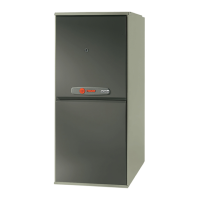
Blower Door Hinge and Bottom Filter Rack Installation
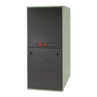
Figure 14
Filter Rack Assembly
Figure 15
VIEW
NGAGEMENT
HOLE DETAIL
Typical both sides
nd blower deck)
Blower Deck
Engagement
Hole
Figure 16
Filter
Rack
urnace
Cabinet
Side
Filter Rac
Retaining
Screw/Pi
Engagement Hole
For
Bottom Return
Filter Rack
Installation With
Figure 17
Airflow
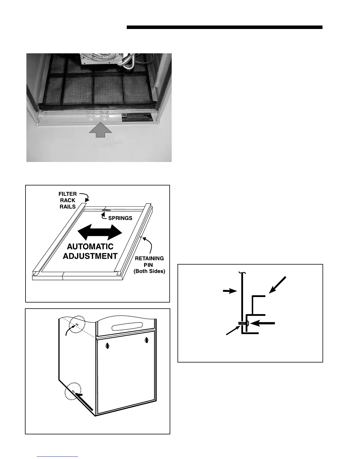
OPTIONAL FILTER RACK INSTALLATION FOR BOTTOM
RETURN
The following checklist should be used when installing a
return filter on an upflow furnace:
a. Remove the filter.
b. Remove the filter rack.
c. Remove the bottom panel.
e. With the filter removed, the filter rack is compressed
and then inserted into the bottom of the furnace. The
retaining screw/pin on each side inserts into engagement
holes at the bottom of the furnace cabinet side. See
Figure 17.
f. Reinstall the furnace filter in the bottom position by
inserting the chamfer end first into the filter rack.
FILTER RACK INSTALLATION FOR SIDE RETURN AIR
ON UPFLOW FURNACES (Left or Right)
The following checklist should be used when installing a right
or left side return filter on an upflow furnace:
a. Remove the filter.
b. Remove the filter rack.
c. Leave the bottom panel in place.
e. Make side cutout by following the directions in the
“Return Air Duct Connections” section on page 11.
e. Compress the filter rack and reinstall in the side
position on the furnace. Confirm that the upper
retaining pin/screw locks into the engagement hole in
the blower deck and the lower pin/screw rests against
the side of the bottom panel. See Figures 16, 18-21.
f. Reinstall the furnace filter in the side position by
inserting the chamfer end first into the filter rack.
Conversion kits for horizontal filters are BAYFLTR203 for 17
1/2" width cabinets, BAYFLTR204 for 21" width cabinets,
and BAYFLTR205 for 24" width cabinets. These include
filters and brackets necessary for horizontal filters. In
addition, optional door kit BAYFLTR206 is also available.
See Figures 23 and 25.
The furnace and the bottom filter rack installation can be
seen in Figure 14.