18-CD26D1-10 19
Installer’s Guide
Table 10
Table 11
PART NUMBERS FOR REPLACEMENT ORIFICES
DRILL
SIZE
PART
NUMBER
DRILL
SIZE
PART
NUMBER
44
45
46
47
48
49
50
ORF00501
ORF00644
ORF00909
ORF00910
ORF01099
ORF00503
ORF00493
54
55
56
57
58
59
ORF00555
ORF00693
ORF00907
ORF00908
ORF01338
ORF01339
If the desired input rate cannot be achieved with a change in
manifold pressure, then the orifices must be changed. LP
installations will require an orifice change.
Important: Reinstall the propane orifices to the same depth as
the orifices supplied with the equipment.
See Table 11 for help in selecting orifices if orifice change is
required. Furnace input rate and temperature rise should be
checked again after changing orifices to confirm the proper
rate for the altitude. For information on high altitude derat-
ing, refer to page 34.
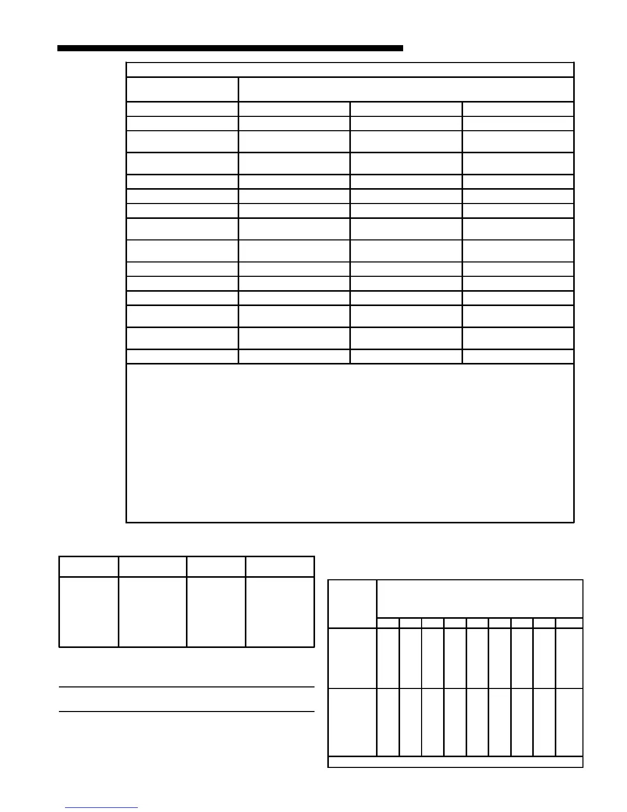
The Vent Length Table (Table 10) above shows the required
vent lengths for installations at various altitudes. An
optional high altitude kit is available for installations above
5000 feet (Installations above 12,000 feet are not allowed).
Table 12
Orifice
Twist Drill
Size If
Installed
At Sea
Level
ALTITUDE ABOVE SEA LEVEL
and Orifice Required At Other Elevations
2000 3000 4000 5000 6000 7000 8000 9000 1000
42
43
44
45
46
47
48
49
42
44
45
46
47
48
49
50
43
44
45
47
47
48
49
50
43
44
45
47
47
49
49
50
43
45
46
47
48
49
50
51
44
45
47
48
48
49
50
51
44
46
47
48
49
50
50
51
45
47
48
49
49
50
51
52
46
47
48
49
50
51
51
52
47
48
50
50
51
52
52
52
50
51
52
53
54
55
56
57
58
51
51
52
54
54
55
56
58
59
51
52
53
54
55
55
56
59
60
51
52
53
54
55
55
57
59
60
51
52
53
54
55
56
57
60
61
52
52
53
54
55
56
57
60
62
52
53
53
54
55
56
58
61
62
52
53
54
55
56
56
59
62
63
53
53
54
55
56
56
59
63
63
53
54
54
55
56
57
60
63
64
From National Fuel Gas Code - Table F-4
VENT LENGTH TABLE
ALTITUDE
MAXIMUM TOTAL EQUIVALENT LENGTH IN FEET
FOR VENT AND INLET AIR (SEE NOTES)
0-7,000 Feet 2 INCH PIPE 2.5 INCH PIPE 3 INCH PIPE
*UH/DH2B060A9V3VA 200 200 200
*UH/DH2B080A9V3VA
*UH/DH2B080A9V4VA
50 120 200
*UH/DH2C100A9V4VA
*UH2C100A9V5VA
Not Allowed 60 200
*UH/DH2D120A9V5VA Not Allowed Not Allowed 200
7,000-9,500 Feet 2 INCH PIPE 2.5 INCH PIPE 3 INCH PIPE
*UH/DH2B060A9V3VA 100 100 100
*UH/DH2B080A9V3VA
*UH/DH2B080A9V4VA
25 60 100
*UH/DH2C100A9V4VA
*UH2C100A9V5VA
Not Allowed 30 100
*UH/DH2D120A9V5VA Not Allowed Not Allowed 100
9,500-12,000 Feet 2 INCH PIPE 2.5 INCH PIPE 3 INCH PIPE
*UH/DH2B060A9V3VA 50 50 50
*UH/DH2B080A9V3VA
*UH/DH2B080A9V4VA
Not Allowed 30 50
*UH/DH2C100A9V4VA
*UH2C100A9V5VA
Not Allowed Not Allowed 50
*UH/DH2D120A9V5VA Not Allowed Not Allowed 50
NOTES: * - First letter may be "A" or "T"
1. Minimum vent length for all models: 3' horizontal or 3' vertical.
2. DO NOT MIX PIPE DIAMETERS IN THE SAME LENGTH OF PIPE OUTSIDE THE FURNACE CABINET (Except
adapters at the top of the furnace). If different inlet and vent pipe sizes are used, the vent pipe must adhere to the
maximum length limit shown in the table above (See note 6 below for exception). The inlet pipe can be of a larger diameter,
but never smaller than the vent pipe.
3. MAXIMUM PIPE LENGTHS MUST NOT BE EXCEEDED! THE LENGTH SHOWN IS NOT A COMBINED TOTAL, IT IS
THE MAXIMUM LENGTH OF EACH (Vent or Inlet air pipes).
4. One SHORT radius 90° elbow is equivalent to 10' of 3" pipe and one LONG radius elbow is equivalent to 6' of 3" pipe.
One 90° elbow is equivalent to 7½' of 2½" pipe or 5' of 2" pipe. Two 45° elbows equal one 90°elbow.
5. The termination tee or bend must be included in the total number of elbows. If the BAYAIR30AVENTA termination kit is
used, the equivalent length of pipe is 5 feet. BAYVENT200B equivalent length is 0 feet.
6. Pipe adapters are field supplied (except for the *UH/DH2D120 models).
7. For Canadian applications ONLY, IPEX 196006 may be used for horizontal and vertical terminations. IPEX 081216, IPEX
081218, and IPEX 081219 may only be used for horizontal vent terminations. Equivalent lengths are IPEX 196009 = 5
feet, IPEX 081216 = 11 feet, IPEX 081218 = 16 feet, and IPEX 081219 = 21 feet