18-CD26D1-10 21
Installer’s Guide
HORIZONTAL VENTING THROUGH WALL
These Furnaces may be installed as direct vent (as
shipped) or as nondirect vent. Installation must con-
form to national, state, and local codes.
The vent & inlet terminals must be located at least 12"
minimum (18" minimum in Canadian applications) above
normally expected snow accumulation level.
Avoid areas where staining or condensate drippage may be a
problem.
Location of the vent/wind terminal should be chosen to meet
the requirements of Figure 42 for either direct or non-direct
vent applications.
PITCH — Venting through the wall must maintain 1/4" per
foot pitched upward to insure that condensate drains back to
the Furnace.
FLUE GAS DEGRADATION — The moisture content of the
flue gas may have a detrimental effect on some building
materials. This can be avoided by using the roof or chimney
venting option. When wall venting is used on any surface that
can be affected by this moisture, it is recommended that a
corrosion resistant shield (24 inches square) be used behind
the vent terminal. This shield can be wood, plastic, sheet
metal, etc. Also, silicone caulk all cracks, seams and joints
within 3 feet of the vent terminal.
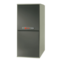
VENT
COMBUSTION
AIR
VENT
VENT
PLATE
VENT
CAP
12" MINIMUM
TO OVERHANG
MAINTAIN 12" (18" FOR CANADA) MINIMUM
CLEARANCE ABOVE HIGHEST ANTICIPATED
SNOW LEVEL OR GRADE WHICHEVER IS GREATER
SCREWS
(4 req.)
ANCHORS
(4 req.)
7.2"
3.2"
Figure 32. BAYVENT200B
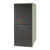
RAIN CA
COMBUSTION AIR
STRAP
(FIELD SUPPLIED)
COMBUSTION
AIR
VENT
ELBOW
(FIELD
SUPPLIED)
VENT
1" + 1/2"
Figure 33
BAYAIR30AVENTA
(Sidewall)
Important: The Commonwealth of Massachusetts
requires compliance with regulation 248 CMR 4.00 and
5.00 for installation of through – the – wall vented gas
appliances as follows:
For all side wall horizontally vented gas fueled
equipment installed in every dwelling, building or
structure used in whole or in part for residential
purposes, including those owned or operated by the
Commonwealth and where the side wall exhaust vent
termination is less than seven (7) feet above finished
grade in the area of the venting, including but not limited
to decks and porches, the following requirements shall be
satisfied:
1. INSTALLATION OF CARBON MONOXIDE
DETECTORS. At the time of installation of the
side wall horizontal vented gas fueled
equipment, the installing plumber or gasfitter
shall observe that a hard wired carbon monoxide
detector with an alarm and battery back-up is
installed on the floor level where the gas
equipment is to be installed. In addition, the
installing plumber or gasfitter shall observe that
a battery operated or hard wired carbon
monoxide detector with an alarm is installed on
each additional level of the dwelling, building or
structure served by the side wall horizontal
vented gas fueled equipment. It shall be the
responsibility of the property owner to secure the
services of qualified licensed professionals for
the installation of hard wired carbon monoxide
detectors
a. In the event that the side wall
horizontally vented gas fueled
equipment is installed in a crawl space
or an attic, the hard wired carbon
monoxide detector with alarm and
battery back-up may be installed on the
next adjacent floor level.
b. In the event that the requirements of
this subdivision can not be met at the
time of completion of installation, the
owner shall have a period of thirty (30)
days to comply with the above
requirements; provided, however, that
during said thirty (30) day period, a
battery operated carbon monoxide
detector with an alarm shall be
installed.
2. APPROVED CARBON MONOXIDE
DETECTORS. Each carbon monoxide detector as
required in accordance with the above provisions
shall comply with NFPA 720 and be ANSI/UL
2034 listed and IAS certified.
CAUTION
!
The vent for this appliance shall not terminate
(1) Over public walways; or
(2) Near sofit vents or crawl space vents or other areas
where condensate or vapor could create a nuisance or
hazard or cause property damage; or
(3) Where condensate vapor could cause damage or could be
detrimental to the operation of regulators, relief valves.
or other equipment.
For Canadian applications only, IPEX 196006, IPEX 081216, IPEX
081218, and IPEX 081219 may be used for horizontal vent terminations.
For Canadian applications only, IPEX 196006, IPEX 081216, IPEX 081218,
and IPEX 081219 may be used for horizontal vent terminations.