16 18-CD26D1-10
Installer’s Guide
For DIRECT VENT APPLICATION: The Furnaces must
be vented to the exterior of the house and combustion air
MUST come through the inlet air pipe FROM OUTSIDE
AIR.
NOTE: BAYVENT200* accessories can be used for inlet and
outlet terminals when the pipes do not exit the structure
together. For Canadian applications ONLY, IPEX 196006
may be used for horizontal and vertical terminations. IPEX
081216, IPEX 081218, and IPEX 081219 may only be used
for horizontal vent terminations.
For NONDIRECT VENT APPLICATION: The Furnace
shall be vented to the exterior of the house, but combustion
air may enter from the surrounding area as long as com-
bustion air requirements are met. (See AIR FOR COM-
BUSTION AND VENTILATION)
FURNACE VENT / INLET PIPE INSTALLATION
There are many different variations of the vent / inlet air pipe
combination. The vent / inlet air combination used for
installation of these Furnaces depends on the needs of the
location. However, these guidelines must be followed:
1. The Furnace must vent outside the structure.
2. Furnace combustion air requirements must be met for
non-direct, single pipe applications.
3. For direct vent application of these Furnaces, the vent
pipe and air inlet pipe do not have to exit in the same air
space or even on the same surface of the structure.
However, the longest individual pipe will decide the value
for the longest allowable equivalent vent/ inlet air length as
shown in the vent length table on page 19.
NOTE: Vent termination kit BAYAIR30AVENTA or
BAYVENT200B may be used in addition to the horizontal and
vertical termination options shown in the following ex-
amples. For Canadian applications ONLY, IPEX 196006 may
be used for horizontal and vertical terminations. IPEX
081216, IPEX 081218, and IPEX 081219 may only be used
for horizontal vent terminations.
The following are EXAMPLES ONLY:
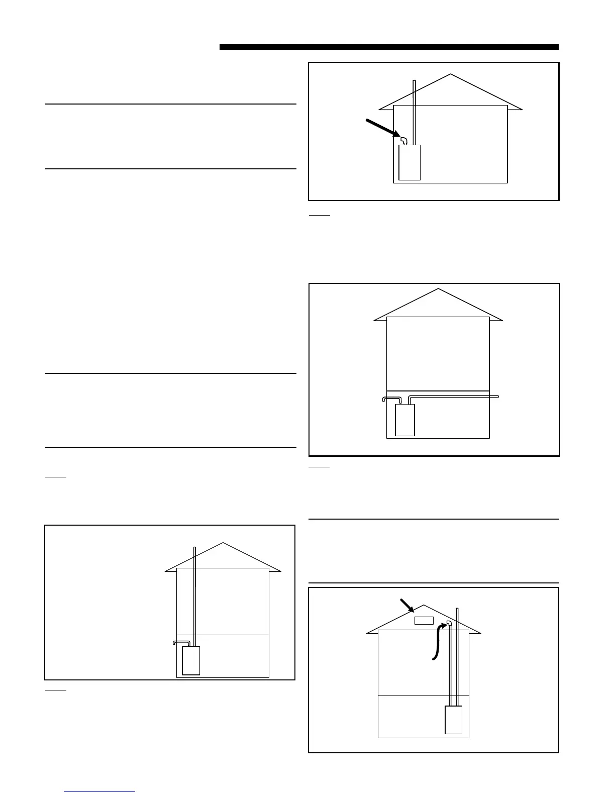
EX. 1 —
Example 1 shows that the vent may go vertical while the inlet
air may be on any side of the structure. The vent pipe would
decide the maximum equivalent length for the pipe depending
on the furnace and pipe size.
EX. 2 —
Example 2 shows the vent pipe exhausting through the roof
and the inlet air coming from the interior of the house. The
inlet air coming from the interior of the house must meet
combustion requirements for area, etc., as shown in the
section AIR FOR COMBUSTION AND VENTILATION in
this Installer’s Guide.
EX. 3 —
Example 3 shows the vent exiting one side of the house while
the inlet air is on the opposite side of the structure. Here the
vent pipe length must be within the allowable length for the
size of Furnace and size of the vent pipe. This example
demonstrates that the pipes do not have to exit on the same
side of the structure.
EX. 4 —
The inlet air does not have to come from outside the structure.
Example 4 shows the inlet air, may come from the attic if the
requirements for combustion air are met as shown in the
section AIR FOR COMBUSTION AND VENTILATION.
NOTE: If only the flue gas pipe is to the outside of the
structure, a straight section of pipe (long enough to exit the
Furnace cabinet) must be attached to the inlet air side with
an elbow (which is 5 to 10 equiv. ft.) installed on the end to
prevent dust and debris from falling directly into the Fur-
nace.
Furnace
ir
nlet
Example 1
Furnace
Air
Inlet
See Note)
Example 2
Furnace
ir
nlet
V
e
Example 3
Furnace
Air
Inlet
Ve
Vent
(See Note)
Example 4