EasyManua.ls Logo

Trane UHEC-IM-7A - Accessory Fan Guard Installation

Trane UHEC-IM-7A
32 pages
Print Icon
To Next Page IconTo Next Page
To Previous Page IconTo Previous Page
Loading...
Characteristic
Unit Size (Kw Rating)
03,05 07 thru 20 25 thru 50
Use this Mounting Bracket:
Model No.
Order No.
A5105
236-723
A5120
236-724
A5150
236-725
Mounting Bracket
Weight
6 Lbs.
(2.7 Kg)
9 Lbs.
(4.1 Kg)
11 Lbs.
(5.0 Kg)
Dimensions
A 19-15/16"
(489 mm)
23"
(584 mm)
26-21/32"
(677 mm)
B 10-1/2"
(267 mm)
12"
(305 mm)
13-1/2"
(343 mm)
C 9-1/4"
(235 mm)
19-1/8"
(486 mm)
19-7/8"
(505 mm)
D 3-31/32"
(101 mm)
7-17/32"
(191 mm)
10-27/32"
(275 mm)
E 5-1/8"
(130 mm)
5-1/8"
(130 mm)
8-11/16"
(221 mm)
Minimum Distance from
Ceiling to Unit
12"
(305 mm)
18"
(457 mm)
18"
(457 mm)
Minimum Distance from
Adjacent Surface to Unit
12"
(305 mm)
12"
(305 mm)
12"
(305 mm)
Minimum Distance from
Floor to Unit *
7 Ft.
(2.4 m)
7 Ft.
(2.4 m)
7 Ft.
(2.4 m)
* Do not exceed unit’s maximum mounting height; see Table 1.
Order No. Model No. Unit Size Number of
Holes
Dim. from Edge Center to Center
Dimension
233-930 OFG-5101 2-5 KW 4 1/4" (6.4mm) 3 3/4" (95mm)
233-932 OFG-5102 7-20 KW 4 1/4" (6.4mm) 4 3/4" (121mm)
233-935 OFG-5103 25-50 KW 6 1/4" (6.4mm) 4 3/4" (121mm)
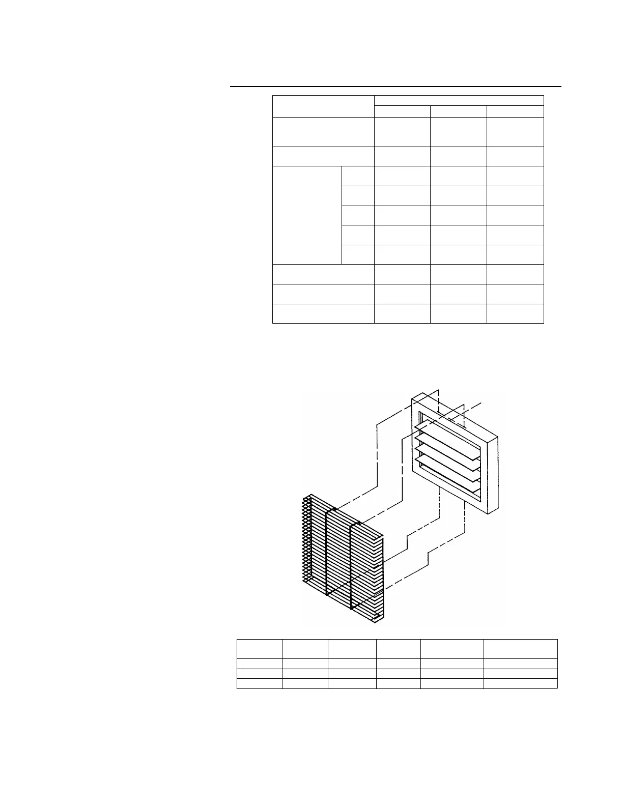
1. For units with existing holes in louver frame, the fan guard snaps into place.
2. To retrofit the fan guard, holes must be drilled 1/8" (3.2mm) diameter as
shown in Figure 2a.
3. OSHA approved.
4. Dimensions in ( ) are in millimeters.
Figure 2a
Accessory Fan Guard Installation
Installation
UHEC-IM-7A 7