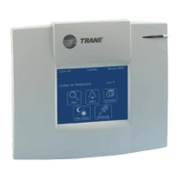
VariTrac Installation
Question: Can both 24Vac power and sensor wiring share the same conduit? ____.
Why or why not? _____________________________________________________
Install Communicating Bypass Damper Assembly
Reference: VariTrac Installation Manual (VAV-SVN03A-EN), Pages 21 through 22
Note:
The communicating sensor/bypass assembly is normally located between the
supply fan and the bypass damper in the least turbulent location possible. It is
recommended that the d stance between the con roller assembly and the nearest
upstream transition be at least 2 to 3 equivalent duct diameters.
i t
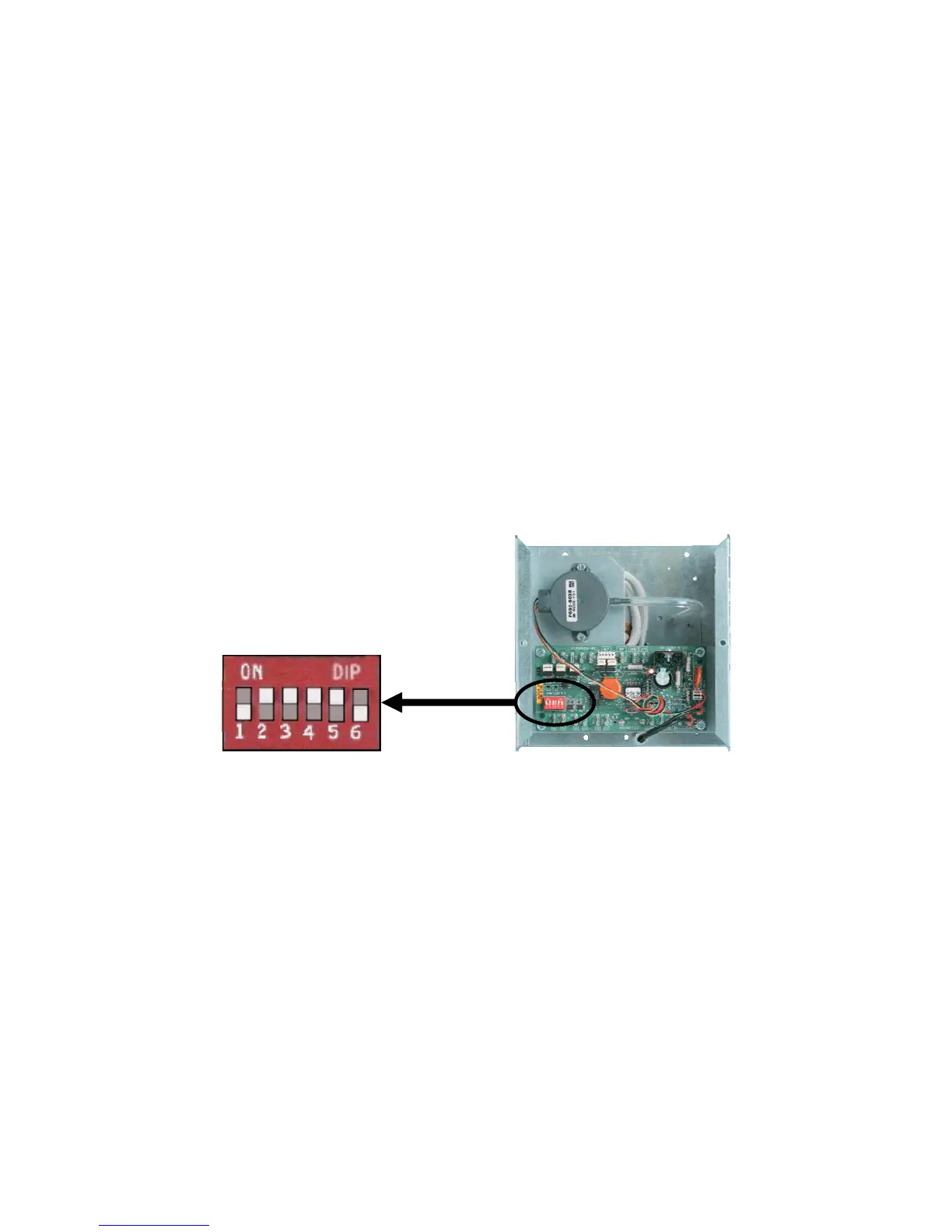
6. Locate the communicating sensor/bypass assembly housing near the VariTac lab equipment
and remove metal cover.
7. Verify address DIP switches on the communicating sensor/bypass UCM board are set to
address ‘ 33 ’.
Note: The communicating sensor assembly UCM address DIP switches are set at the
factory to Address 33.
8. Connect the communications link wiring to terminalsTB2-1 and TB2-2, TB2-3 and TB-2-4
using the pre-configured wiring harness provided. Observe (+) and (-) polarity on the link.
Note: A pre-configured wiring harness is provided to connect both 24Vac and the
communications link to the communicating bypass/damper UCM.
9. Connect 24Vac power to terminals TB1-1 (24V) and TB-2 (ground) on the UCM
Caution: It is not recommended that 24Vac power be shared between controllers.
However, if controllers share a common transformer, polarity must be observed on 24Vac
connections on UCMs that share the same transformer.
03- VariTrac Installation Workshop.doc 3-4