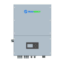
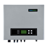
The document describes the Tranenergy TRN series of solar inverters, which are advanced and efficient inverters designed to ensure a stable power supply for various applications. These inverters are transformerless, making them compact and efficient.
Function Description
The TRN series inverters convert direct current (DC) from solar panels into alternating current (AC) for use in homes or businesses. They are designed to operate reliably and efficiently, with various modes for different operating conditions. The inverters include multiple safety features to protect against electrical hazards and ensure stable operation. They also offer communication interfaces for monitoring and control, allowing users to track performance and manage the system remotely.
The inverters support both single-phase and three-phase configurations, depending on the model. They are equipped with Maximum Power Point Tracking (MPPT) to optimize power harvest from the solar panels. The system includes a boost and inverter module, along with various control and protection circuits to manage power flow and ensure safety.
Important Technical Specifications
The TRN series includes several models, ranging from TRN010KTL to TRN025KTL, with varying power outputs and specifications.
General Specifications:
- Rated AC Power: Ranges from 10000 W (TRN010KTL) to 25000 W (TRN025KTL).
- Maximum AC Power: Ranges from 12000 VA (TRN010KTL) to 27000 VA (TRN025KTL).
- Maximum Input Power: Ranges from 11000 W (TRN010KTL) to 27000 W (TRN025KTL).
- Maximum DC Voltage in an Open Circuit: 1000 Vdc for all models.
- MPPT Voltage Range: 250 - 800 Vdc / 600 Vdc for all models.
- Maximum Input Current: 10 Adc / 10 Adc for smaller models, up to 20 Adc / 20 Adc for larger models.
- Startup Voltage: 200 Vdc for all models.
- DC Switch: Integrated for all models.
- Initial Feeding Voltage: 300 Vdc for all models.
- Number of Inputs: 1+1 for smaller models, up to 2+2 for larger models.
- MPPT Number: 2 for all models.
- Operating Voltage: 230 Vac for all models.
- Number of Grid Phases: 3 for all models.
- Voltage Range: 180 - 270 Vac / 310 Vac - 470 Vac.
- Frequency Range: 50 Hz, 60 Hz / -5 Hz ... +5 Hz.
- Power Factor: >0.8, -0.8 controllable.
- Maximum Current: Ranges from 15.5 Aac (TRN010KTL) to 38 Aac (TRN025KTL).
- DC Current Injection (max.): <1% for all models.
- Current Harmonic Distortion (THDi): <3% for all models.
- Maximum Efficiency: >98.1% for all models.
- MPPT Efficiency: >99.9% for all models.
- European Efficiency: >97.6% for all models.
- Switching Plan: Self-commutated, transformerless.
- Off-grid Protection: Yes for all models.
- Night Power Consumption: <0.2 W for all models.
- Detecting Earth Leakage: Yes for all models.
- Heat Dissipation: Smart Fan cooling.
Mechanical Specifications:
- Dimensions: 520 x 180 x 700 mm.
- Weight: 35 kg (TRN010KTL, TRN012KTL), 35 kg (TRN015KTL, TRN017KTL), 35 kg (TRN020KTL, TRN023KTL), 36 kg (TRN025KTL).
- Protection Class: IP65.
- Display: LCD.
- Data Interface: RS232 / RS_485 / RS_422 / Ethernet / WiFi / GPRS / USB.
- Thermal Protection: Yes.
- Noise Emission: <45dB.
- Ambient Operating Temperature: -25 °C - +60 °C.
- Casing: Aluminium.
Certifications:
- VDE AR-N-4105, VDE 0126-1-1+A1, CE, G83/2, UTE C15-712, MEA, PEA, AS4777, NB/T32004-2013.
Usage Features
The TRN series inverters are designed for ease of use and comprehensive monitoring.
Installation:
- Mounting: The inverter should be mounted on a solid wall using expansion pipes and screws. Specific dimensions for drilling holes are provided.
- Clearance: Maintain at least 300mm of clearance around the inverter for proper ventilation.
- Electrical Connections:
- AC Output: Connect the AC output terminal to the grid using appropriate cables (e.g., 10mm²). Ensure the AC breaker is switched off before connection.
- PV Generator (DC Input): Connect the PV modules to the DC input terminals. Use an individual manual DC breaker for each inverter. Ensure correct polarity and voltage. The inverter has two MPPT trackers (A & B route) for flexible PV array configuration.
- Safety: Always disconnect the AC and DC power before installation or maintenance.
Operation Modes:
- Wait Mode: The inverter waits until the input voltage is above 300Vdc and below 910Vdc to start.
- Check Mode: The inverter performs self-check, HCT device, GFCI device, relay, fan, and soft start.
- Normal Mode: The inverter operates normally, converting DC to AC. It will adjust energy production based on advanced MPPT technology.
- Fault Mode: If a fault occurs, the inverter will stop generating power and display fault information on the LCD.
- Flash Mode: The inverter runs in a mode above flash command, rewriting firmware in DSP flash.
- Shut Down: The inverter shuts down automatically if PV input voltage is less than 230Vdc or due to other fault occurrences.
Human Machine Interface (HMI):
- LEDs: Green LED (working normally), Yellow LED (communication), Red LED (fault).
- LCD Display: A 240x160 mono LCD displays system information, including working status, energy yield, inverter state, settings, and log data.
- Buttons: RUN, FAULT, COM, UP, ESC, ENTER, DOWN buttons for navigation and control.
- Function Keys: OK Button (confirm selection), UP Button (move cursor up or increase values), DOWN Button (move cursor down or decrease values), ESC Button (exit current menu), ENTER Button (enter menu).
Monitoring and Communication:
- Local Monitoring: The LCD display provides real-time data and status.
- Remote Monitoring: The inverter supports RS-232, RS-485/422, WiFi/GPRS/Ethernet, and USB for remote monitoring.
- RS-232: For communication between PC and one TRN series inverter.
- RS-485/422: For multi-inverter communication, allowing up to 32 inverters to be monitored simultaneously.
- USB: For maintenance engineers to realize burning and updating of PCU firmware.
- WiFi/GPRS/Ethernet: For web browser and mobile app access to monitor information.
Maintenance Features
The TRN series inverters are designed for minimal maintenance, but some routine checks are recommended.
Routine Maintenance:
- Cleaning: Regularly clean the inverter's external surface and heat sink to ensure proper air flow and prevent dust accumulation. Use a compressed air, soft cloth, or brush. Do not use water, corrosive chemicals, or strong detergents.
- Fault Handling: In case of a fault, the inverter will display an error message on the LCD. Refer to Appendix A (FAQ) for troubleshooting.
- Qualified Personnel: Maintenance and repair should only be performed by qualified personnel. The inverter contains hazardous voltages even when it is disconnected from PV modules and the grid.
- DC Bus Voltage: The DC bus voltage might be lower than 48V before starting work on the electronic system inside the cabinet.
Warranty:
- Standard Warranty Period: 120 months (10.5 years) from the date of installation or 126 months (10.5 years) from the date of shipment for Tranenergy Co., Ltd.
- Extension of Warranty: Purchasers may apply for a warranty extension up to 12 months following the installation date or 24 months from the date of shipment.
- Liability Insurance: Tranenergy inverters are insured up to a maximum of $3,000,000 by Chubb Insurance Company Limited.
- Warranty Claim Procedure: Report defective devices with a brief error description and serial number to Tranenergy service mail or service hotline. Provide product model, serial number, error message on LCD, detailed system information, previous claims/exchanges, copy of invoice, and warranty certificate.
- Exclusion of Warranty Claims: Warranty claims may be excluded if the product is modified, repaired, or altered without authorization; if there are damages due to incorrect installation, operation, or maintenance; or if the product is used in an unsuitable environment.
Service after Warranty Expiration:
- Tranenergy charges an on-site service fee, parts, labor cost, and logistic fee for end-user services after warranty expiration.
Contact Information:
- Tranenergy Co., Ltd. (China), Tranenergy UK Ltd, Tranenergy Benelux Service Center, Tranenergy Australia Service Center. Contact details (address, email, hotline) are provided in the manual.