EasyManua.ls Logo

Transpak TP-6000-1 User Manual

Transpak TP-6000-1
121 pages
To Next Page IconTo Next Page
Page #1 background imageLoading...
Page #1 background image
SPARE PARTS LIST
OPERATION MANUAL
TP-6000-1
STRAPPING MACHINE
AUTOMATIC POLYPROPYLENE
&
TP-6000CE1
K
EE
P
I
T
WE
L
L
I
M
P
OR
TA
N
T
!
TP-6000CE3
TP-6000-3
Question and Answer IconNeed help?

Do you have a question about the Transpak TP-6000-1 and is the answer not in the manual?

Transpak TP-6000-1 Specifications

General IconGeneral
BrandTranspak
ModelTP-6000-1
CategoryPackaging equipment
LanguageEnglish

Summary

Operation Manual & Spare Parts List

Safety Instructions

Pre-Operation Safety Guidelines

Precautions before operating the machine, including eye protection and gloves.

During Operation & Post-Operation

Safety measures during use and procedures after operation.

Safety Signs and Maintenance

Explanation of warning symbols and safety for machine maintenance.

Construction and Function of Units

Major Machine Units Overview

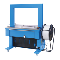
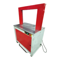
Description of key units like strapping head, bandway, and control unit.

Technical Data

Control Panel Operation

Standard and CE Version Controls

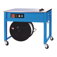
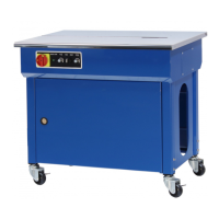
Description of control panel functions for different versions.

Electric Control Unit Details

Three Phase and Single Phase Components

Details on timers and components for different phases.

How to Load P.P. Strap

Strap Loading Procedure Steps

Step-by-step guide for loading the strapping material.

Operation and Recommendations

Machine Operation Steps

Detailed sequence for operating the strapping machine.

Tips for Trouble-Free Operation

Recommendations for smooth and reliable machine performance.

Machine Adjustments

Tension and Heater Settings

Adjusting strap tension strength and heater temperature.

Feed and Take-Up Mechanism Adjustment

Adjusting Strap Feed Clearance

Procedure for setting correct clearance between roller springs and hooks.

Limit Switches and Control Unit Movement

Understanding Limit Switch Functions

Explanation of LS1, LS2, LS3 roles in machine operation.

Accumulator Box Strap Adjustment

Installation of Arch Unit

Arch Unit Installation Steps

Step-by-step guide for installing the arch unit and bandways.

Wiring Diagrams

TP-6000 Series Wiring Schematics

Electrical wiring diagrams for various TP-6000 models.

Troubleshooting Common Issues

Machine Operation Problems and Remedies

Solutions for common issues like no power, unsealed straps, and tension problems.

Bill of Material Explanation

Strapping Head Unit Parts

Cam Group Components

Parts list and diagram for the Cam Group assembly.

Slide Table Group Parts

Slide Table Assembly Details

Exploded view and parts list for the Slide Table Group.

Press Group Parts

Press Assembly Components

Parts breakdown and diagram for the Press Group.

Heater Group Parts

Heater Assembly Components

Parts breakdown and diagram for the Heater Group.

Reel Unit Components

Reel Guard and Control Group

Parts for the Reel Guard and Reel Control Group.

Tension Group Parts

Tension Assembly Components

Parts breakdown and diagram for the Tension Group.

Body Frame Unit Components

Upper Table Front Set Components

Parts for various Upper Table Front Set assemblies.

Electric Control Unit

Electric Control Groups and Boxes

Details on electric control groups and associated box components.

Chute Arch Group Parts

Arch Assembly Components

Parts list and diagram for the Chute Arch Assembly.

Accumulator Unit Components

Accumulator and Box Group Parts

Parts lists for Accumulator Unit and Accumulator Box Group.

Reel Unit Components

Reel Guard and Control Group Parts

Parts for the Reel Guard and Reel Control Group.

Body Frame Unit Components

Body Frame Group Parts

Components of the main Body Frame Group.

Related product manuals