EasyManua.ls Logo

Traulsen RBC200 User Manual

Traulsen RBC200
28 pages
To Next Page IconTo Next Page
Page #1 background imageLoading...
Page #1 background image
Quality Refrigeration
OWNER’S MANUAL
Instructions for the installation, operation,
and maintenance of Blast Chiller Models:
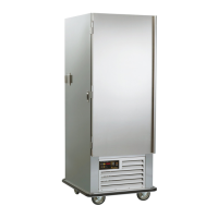
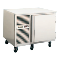
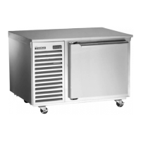
RBC50 (50 lb. capacity undercounter model)
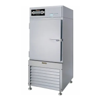
RBC100 (100 lb. capacity reach-in model)
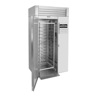
RBC200 (200 lb. capacity roll-in model)
RBC200RT (200 lb. capacity roll-thru model)
RBC400 (400 lb. capacity roll-in model)
RBC400RT (400 lb. capacity roll-thru model)
This Traulsen unit is built to our highest quality standards. We build our refrigerators, freezers, blast
chillers and heated cabinets this way as a matter of pride. This philosophy has made Traulsen the
leader in commercial refrigeration since 1938. We thank you for your choice and confidence in
Traulsen equipment and we know you will receive many years of utility from this equipment.
All Traulsen units are placed on a permanent record file with the service department. In the event
of any future questions you may have, please refer to the model and serial number found on the name
tag affixed to the unit. Should you need service, however, call us on our toll free number, 800-825-
8220 between 7:30 am and 4:30 pm CST, Monday thru Friday. It is our pleasure to help and assist
you in every possible way.
FORM NUMBER TR35850 REV. 4/07 P/N 375-60217-00
IMPORTANT WARRANTY NOTES
RBC50 & RBC100 Owner/Operators
Please Contact (800) 825-8220 ext. #6115 upon start-up to register your warranty
RB200/RBC200RT & RBC400/RBC400RT Owner/Operators
Please Contact (800) 825-8220 ext. #6112 after installation but before start-up in order to register
your warranty and arrange for a mandatory free Installation Validation & Service Check
(allow at least 72 hours from time of call for this to be performed)
Contact your local Hobart/Traulsen sales representative to arrange for a free on-site
demonstration (after warranty registration and/or installation validation)

Other manuals for Traulsen RBC200

Questions and Answers:

Traulsen RBC200 Specifications

RBC200

Electrical Data IconElectrical Data
voltage115/60/1
full load amperes15.2
minimum circuit ampacity20
wattage1725
Refrigeration Data IconRefrigeration Data
refrigerantR404a
BTU/HR - HP3880 - 3/4 HP
heat load - BTU/HR7000
suction line3/8 in. (.95 cm)
liquid line1/4 in. (.63 cm)
Remote Condenser IconRemote Condenser
refrigerantR404a
voltage208-230/60/1
recommended BTU/HR - HP18, 700 - 4 HP
suction line at blast chill unit7/8 in. (2.2 cm)
liquid line at blast chill unit1/2 in. (1.3 cm)
suction line on remote condenser1.125 in. (2.9 cm)
liquid line on remote condenser1/2 in. (1.3 cm)
Weight and Dimensions IconWeight and Dimensions
net capacity35 cu. ft. (990.5 l)
length overall48.5 in. (123.2 cm)
depth - cabinet only34 in. (86.4 cm)
depth - with door open 90°65.125 in. (165.4 cm)
depth - overall37.5 in. (95.3 cm)
clear door width27.25 in. (69.2 cm)
clear door height72.625 in. (184.5 cm)
height - overall89.5 in. (227.3 cm)

RBC200RT

Electrical Data IconElectrical Data
voltage115/60/1
full load amperes15.2
minimum circuit ampacity20
wattage1725
Refrigeration Data IconRefrigeration Data
refrigerantR404a
BTU/HR - HP3880 - 3/4 HP
heat load - BTU/HR7000
suction line3/8 in. (.95 cm)
liquid line1/4 in. (.63 cm)
Remote Condenser IconRemote Condenser
refrigerantR404a
voltage208-230/60/1
recommended BTU/HR - HP18, 700 - 4 HP
suction line at blast chill unit7/8 in. (2.2 cm)
liquid line at blast chill unit1/2 in. (1.3 cm)
suction line on remote condenser1.125 in. (2.9 cm)
liquid line on remote condenser1/2 in. (1.3 cm)
Weight and Dimensions IconWeight and Dimensions
net capacity35 cu. ft. (990.5 l)
length overall48.5 in. (123.2 cm)
depth - cabinet only34 in. (86.4 cm)
depth - with door open 90°96.25 in. (244.5 cm)
depth - overall41.125 in. (104.5 cm)
clear door width27.25 in. (69.2 cm)
clear door height72.625 in. (184.5 cm)
height - overall89.5 in. (227.3 cm)

Summary

I. INTRODUCTION

II. RECEIPT INSPECTION

III. INSTALLATION

Site Selection and Packaging

Proper location selection and unpacking procedures for safe unit placement.

Installing Legs, Casters, and Assembly

Steps for attaching legs/casters and assembling multi-unit models.

Wiring Diagram and Electrical Requirements

Information on electrical connections, circuit requirements, and wiring diagrams.

Proper Clearances and Condensate Removal

Guidelines for maintaining adequate space and managing condensate drainage.

Remote Condensing Units and Special Procedures

Covers remote unit requirements, cut-out settings, sealing, and ON/OFF switch.

RBC50 Control Panel Installation

Step-by-step guide for installing the control panel on the RBC50 model.

IV. CARE & MAINTENANCE

Cleaning the Condenser and Printer Supplies

Instructions for cleaning the condenser coil and details on printer supplies.

Cleaning Exterior and Interior Surfaces

Methods for cleaning the unit's exterior stainless steel and interior components.

V. OTHER

Service Agency Check, Training, and Information

Covers required inspections, operator training, service contacts, and demonstrations.

VI. THE SMARTCHILL® CONTROL

Control Overview, Basics, and Startup

Explains the SmartChill control features, basic operation, and startup screen.

Control Modes, Printing, and Features

Details on printing capabilities, over temperature alarms, power interruptions, and EZ Start.

VII. OPERATING THE BLAST CHILL CONTROL

Starting a Chill Cycle by Temperature

Step-by-step instructions for initiating a blast chill cycle using temperature targets.

Starting a Chill Cycle by Time

Guide on how to perform a blast chill cycle based on a set duration.

Starting a Chill Cycle by Product

Process for selecting and chilling products using pre-programmed parameters.

Hold Mode and Defrost Operations

Explains how to use the refrigerated hold mode and initiate manual defrost cycles.

Printing Data and Setup Procedures

Instructions for printing reports and setting up products, users, and system parameters.

VIII. SMARTCHILL™ COMMUNICATIONS

System Requirements and Hardware Connection

Outlines the necessary PC system requirements and hardware connection for data communication.

IX. GLOSSARY

X. REPLACEMENT PARTS LIST

XI. SUMMARY OF ERROR MESSAGES

XII. WARRANTY INFORMATION

XIII. MECHANICAL TROUBLE SHOOTING GUIDE

Related product manuals