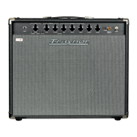
2
1
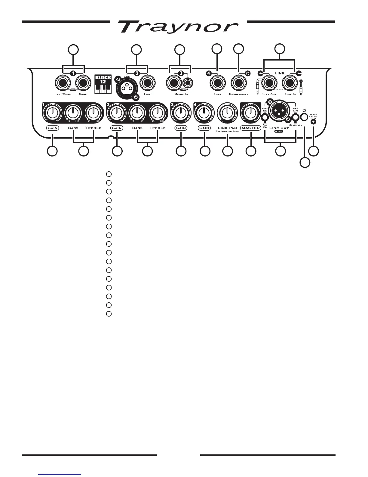
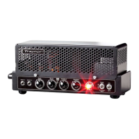
Status LED and Power Switch (switch located on rear)
2
Input clip LED – Channel 1-3
3
Channel 1 Input Jacks –¼-inchTRSjacks
4
Channel 1 Gain Control
5
Channel 1 Tone Controls – Bass and Treble
6
Channel 2 Input Jacks –BalancedXLRand¼-inchTRSjacks
7
Channel 2 Gain Control
8
Channel 2 Tone Controls – Bass and Treble
9
Channel 3 Input Jacks –¼-inchandjacks
10
Channel 3 Gain Control
11
Channel 4 Input Jack –¼-inchTRSjack
12
Channel 4 Gain Control
13
Master Volume Control
14
Headphones Jack –¼-inchTRSjack
15
Link Pan / Balance Control
16
Line Out –BalancedXLRjack,Pre/PostSelectorandGroundLift
17
Link Jacks
Power
1. Power/Status LED
ThepowerLEDdisplaysthestatusandconditionoftheamplier.Whenpoweringupthe
TraynorBlockamplier,theLEDwillilluminateredforafewmomentsandthenturnblue
whentheampisreadytogo.Ifafaultisdetected,theLEDwillconstantlyilluminatered.
Input Channels
2. Input clip LED
TheinputclipLEDlocatednearthePower/StatusLED,hasbeendesignedtomonitorChan-
nels 1-3 for clipping. It will turn on when the input signal from an audio source is too hot (or
thegainissettoohigh).AdjustthechannelsindividuallywhileplayinguntiltheLEDstopsin-
dicatingclipping(it’sokayiftheLEDblinksbriey).
93
8
14
5
6
11
1612
1
24 7 10 15
17
13