14
EN
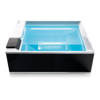
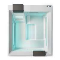
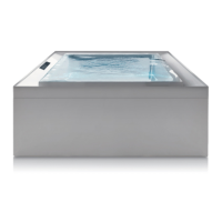
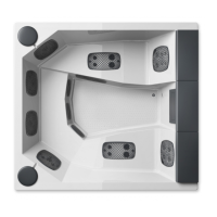
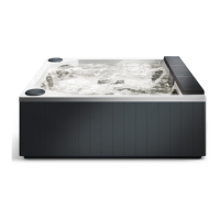
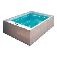
Shadow minipool
N
L
Installation
7
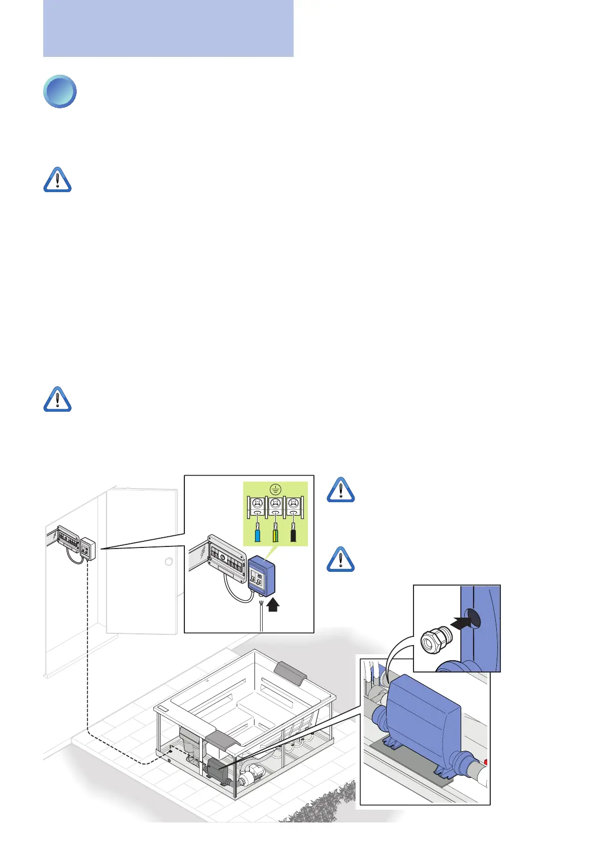
ELECTRICAL CONNECTIONS
The Treesse minipools are built in compliance with European laws (EN 60 335-2-60) and are tested during production
to ensure the safety of the installer and user.
The connection must be made by an experienced, qualied electrician.
All electrical connections must be made only after disconnecting the electricity in the work area.
The electrical connection must be:
• Performed in a xed and permanent manner, without intermediate splices, in accordance with regulations of the
country of installation.
• Sufcient for the current absorbed by the bathtub (see technical specications).
• Provided with a functioning ground as per current regulations.
• Protected against splashing water, then placed in a dedicated room, closed and sheltered from the weather.
• Controlled by a multi-pole switch with a contact gap of at least 3 mm and a breaking capacity equal to 60A (or in
any case adequate for the absorption of the bathtub).
• Controlled by a differential switch no larger than 30mA.
The control unit's power supply cable must be of the H05 type with three wires (single-phase 230V) whose gauges
are adequate for the absorption of the minipool (see "Pre-installation sheet"). Its size depends on the absorbed
current and the distance of the minipool from the main electrical cabinet.
In addition, if the minipool is installed outdoors, the power cord from the main electrical panel to the minipool must
pass through an underground duct, without splices and adequately protected against freezing.
The Manufacturer is not responsible for connections made in a way that does not comply with local codes, the
specicationsinthismanualortamperingwithanyelectricalcomponentoftheminipool.
When the connections have been made, verify
the proper operation of the differential switch by
pressing the TEST key.
NB: to correctly connect the power cable, use a
cable gland (not supplied), suitable for the diam-
eter of the hole and the diameter of the cable.