IQ422, IQ4NC/00, IQ4NC/12 Controllers Installation Instructions - Mounting TG201264 Issue 12, 04-Feb-2020. Applies to v4.30 5
Installation Instructions - Mounting IQ422, IQ4NC/00, IQ4NC/12
8
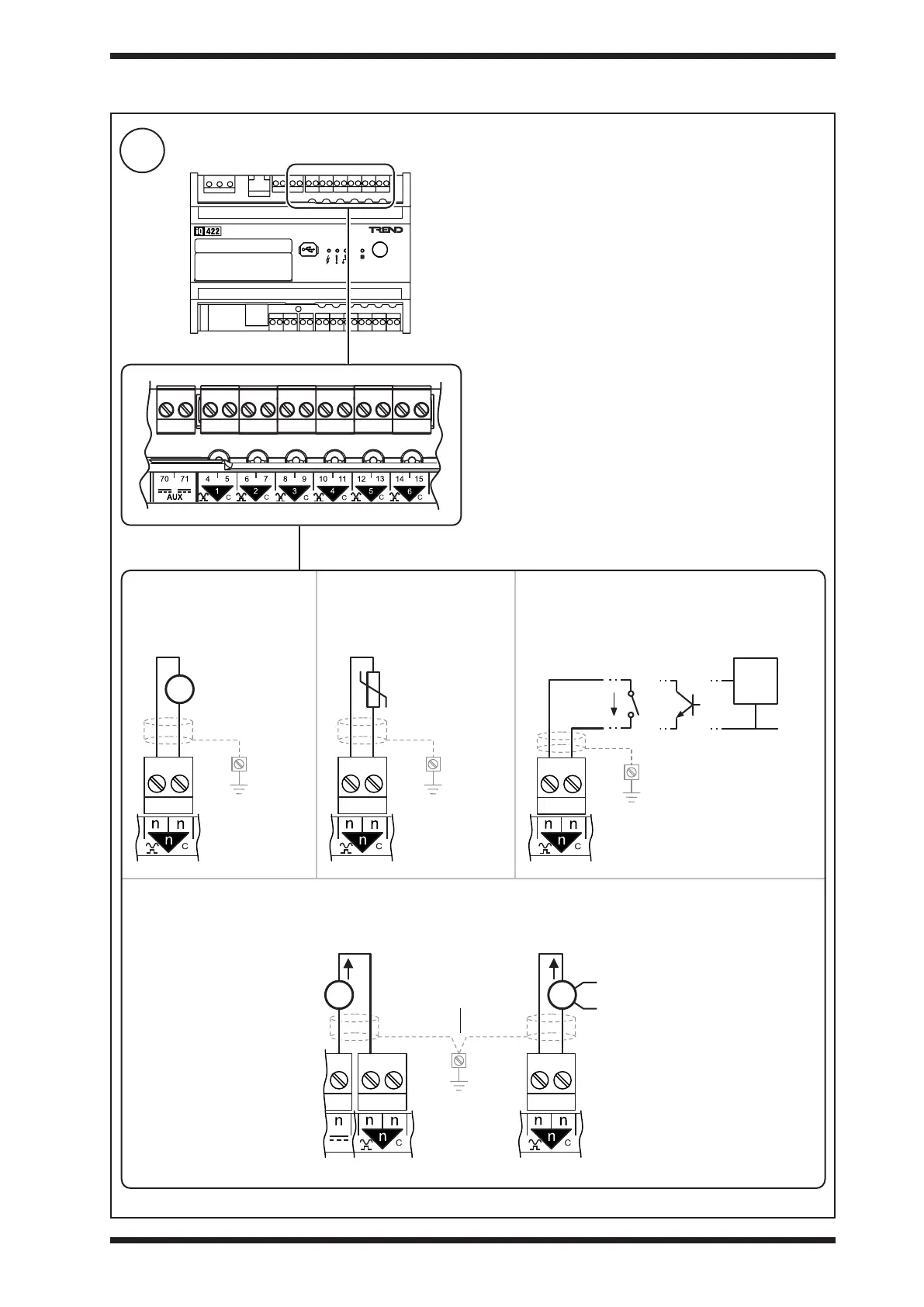
Connect Universal Inputs IN1 to IN6 (if required - not applicable to IQ4NC/00/..)
3 INSTALLATION (continued)
Terminal size: 0.14 to 2.5 mm
2
(22 to 12 AWG)
Terminal screw torque: 0.45 to 0.62 Nm (4 to 5.5 lb.in).
For UL rating use 22 to 14 AWG - Cu only cable. TP/1/1/22/
HF/200 (Belden 8761) cable recommended for all inputs.
Screened cable is not generally required unless the cable
passes through electrically noisy environments. Where it
is used the screen must be connected to the local panel/
enclosure ground and left unterminated at the far end.
Note: The input type (i.e. voltage, thermistor, digital or current)
is dened in the controller’s strategy.
Current input
ensure correct polarity
Thermistor 10 kohm
Potentiometer 1 to 11 kohm
ensure correct polarity
Auxiliary output supply
(AUX) - see step 10.
panel/enclosure
ground
Externally poweredLoop powered
External
Power
Supply
ThermistorVoltage Digital
0 to 10 V
panel/enclosure
ground
panel/enclosure
ground
volt free
contact
open
collector
logic
circuit
panel/enclosure
ground
ensure correct polarity
270 μA
TTL /
CMOS
0V