EN - T8
-15-
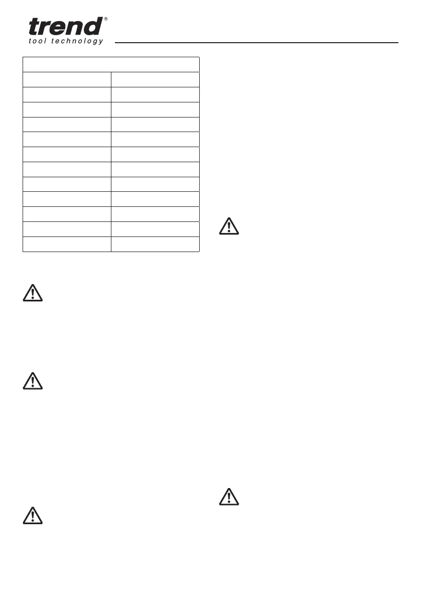
SPEED SELECTION CHART
DIAL SETTING APPROXIMATE RPM
1 10,000
2 11,500
3 13,000
4 14,500
5 16,000
6 18,000
7 20,000
8 21,500
9 23,000
10 24,000
Max 26,000
The speeds in this chart are approximate and are for
reference only. Your router may not produce the exact
speed listed for the dial setting.
WARNING: Always follow the cutter
manufacturer’s speed recommendations as some
bit designs require specific speeds for safety or
performance.
If you are unsure of the proper speed or are experiencing
any type of problem, contact the cutter manufacturer.
LED Worklights - (Fig. F)
CAUTION: Do not stare into worklight.
Serious eye injury could result.
Two LED worklights (57) are located next to the collet
assembly (6).
1. The worklights (57) will constantly illuminate when the
router is connected to the mains power supply.
2. To switch off the worklights the router must be
disconnected from mains power supply.
NOTE: The worklight is for lighting the immediate work
surface and is not intended to be used as a flashlight.
Moulding Natural Timbers
WARNING: When routing always lock the
plunge locking lever.
When edge moulding natural timbers, always mould the
end grain first, followed by the long grain. This ensures
that if there is breakout, it will be removed when the long
grain is routed.
Adjusting the Depth of Cut - (Fig. A, E)
1. Place the router with cutter fitted on to the workpiece.
2. Set the depth stop turret (7) as required.
3. Loosen the locking knob (4) securing the depth stop (3).
4. Lower the router slowly until the cutter touches the
workpiece and secure it in place by locking the plunge
with the plunge locking lever (16).
5. Set the required depth by adjusting the distance
between the bottom of the depth stop and the depth
stop turret.
6. Tighten the locking knob to secure the depth stop.
NOTE: By rotating the depth stop turret, eight depth
settings can be quickly made.
Direction Of Feed - (Fig. L)
WARNING: Avoid climb-cutting (cutting in
direction opposite than shown in Fig. L). Climb-cutting
increases the chance for loss of control resulting in
possible injury. When climb-cutting is required (backing
around a corner), exercise extreme caution to maintain
control of router. Make smaller cuts and remove minimal
material with each pass.
The direction of feed is very important when routing and
can make the difference between a successful job and
a ruined project. Fig. L show proper direction of feed for
most cuts.
1. When routing along an edge, the direction of the
router travel should be against that of the rotation of
the cutter. This will create the correct cutting action
and prevent the cutter from snatching. It will also pull
the router towards the workpiece and the side fence or
guide bearing will be less likely to wander from the edge
of the workpiece.
Feed Speed
The speed at which the cutter is fed into the wood must
not be too fast that the motor slows down, or too slow
that the cutter leaves burn marks on the face of the
wood.
NOTE: Practice judging the speed by listening to the
sound of the motor when routing.
Using a Side Fence - (Fig. M)
CAUTION: Ensure working position is
comfortable and at a suitable working height.
1. Ensure the wing bolts (28) are fully released. Slide the
guide rods (26) into the routing base (8) and tighten the
wing bolts.
2. Adjust the fence fine adjustment knob (29) to the required
distance and clamp in place with the wing bolts (28).