EN - T8
-14-
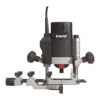
Using the Router - (Fig. A, L)
CAUTION: Turn the router on before plunging
the cutter head into the workpiece.
CAUTION:
• Excessive cutting may cause overload of the motor
or difficulty in controlling the tool, the depth of cut
should not be more than 15mm at a pass when cutting
grooves with a 8mm diameter bit.
• When cutting grooves with a 20mm diameter bit, the
depth of cut should not be more than 5mm at a pass.
• For extra deep grooving, make two or three passes
with progressively deeper bit settings.
CAUTION: After long periods of working at
low speeds, allow the machine to cool down by running
it for three minutes at maximum speed, with no load.
All common routing tasks can be performed with the
plunge cut router on all types of wood and plastic:
• Grooving
• Rebating
• Recessing
• Veining
• Profiling
To prevent overload of the tool by using the wrong speed
selection, follow the recommended settings below:
MATERIAL CUTTER DIAMETER
10 – 30mm 30 – 50mm 50 – 65*mm
SPEED SELECTION
Hardwood 11 - 5 6 - 2 5 - 2
Softwood 11 - 6 11 - 5 5 - 2
Chipboard
Faced
11 - 6 11 - 4 n / a
Plastic 11 - 5 11 - 4 n / a
* Do not use cutters larger than 50mm unless the router
is fitted in a router table.
NOTE: Only carbide tipped cutters should be used on
panels faced with plastic laminates. The hard laminates
will quickly dull steel cutters.
NOTE: For better plunge sliding movement, frequently
clean the columns of dust or debris. If the plunging
movement is not moving as smooth as desired, lubricate
the columns with a dry Teflon lubricant.
1. After setting the cutting depth as described, locate the
router such that the cutter is directly over the place you
will be cutting.
2. With the router running, lower the unit smoothly down
into the workpiece. DO NOT JAM THE ROUTER DOWN.
3. When the tool reaches the pre set depth, turn the
plunge locking lever (16) to lock.
4. When you have finished routing, push the plunge
locking lever (16) to unlock and let the spring lift the
router directly out of the workpiece.
5. Always feed the router opposite to the direction in
which the cutter is rotating. Refer to Fig. L.
On/Off Trigger Switch - (Fig. A)
WARNING: To reduce the risk of serious
personal injury, turn unit off and disconnect it from power
source before making any adjustments or removing/
installing attachments or accessories. An accidental
start-up can cause injury.
1. To turn the unit on, press the trigger release button
(20) and then squeeze the on/off trigger switch (19).
Continue to squeeze the trigger switch for continuous
running.
2. To turn the unit off release the trigger.
Variable Speed Dial - (Fig. A)
WARNING: If the speed control ceases
to operate, or is intermittent, stop using the tool
immediately. Please contact Trend Tool Technology Ltd
or authorized service facility for repair.
NOTICE: The router is equipped with electronics to
monitor and maintain the speed of the tool while cutting.
In low and medium speed operation, the speed control
prevents the motor speed from decreasing. If you expect
to hear a speed change and continue to load the motor,
you could damage the motor by overheating. Reduce
the depth of cut and/or slow the feed rate to prevent tool
damage.
Refer to the Speed Selection Chart to choose a router
speed. Turn the speed dial (1) to control router speed.
The lowest speed is 10,000 and the highest speed is
26,000 rpm using the speed dial (1).
1. Turn the speed dial to the required position. The dial
is numbered from 1 – Max. and corresponds to router
speeds of 10,000 rpm to 26,000 rpm.
2. Use the slower settings for large diameter cutters and
the faster settings for small diameter cutters.
3. The correct setting will also depend on the density of
the material, depth of cut and feed speed of the router.
NOTE: A noticeable loss of motor rpm means motor
overload